
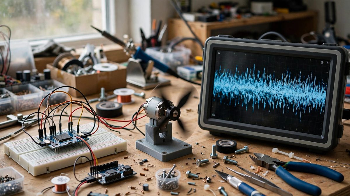
A raw gyroscope signal looks nothing like the smooth rotation it represents. Zoom in and the trace is a thick band of jitter: vibration from motors, electrical noise from the power rail, quantization chatter from the sensor itself, all riding on top of the real angular velocity. Feed that raw signal straight into a balance loop or a heading estimator and the controller chases the noise, heating motors and twitching the mechanism. A low-pass filter is the standard fix, and it is simple enough to implement in a few lines. The craft lies in choosing the cutoff so the filter removes noise without eating the motion you are trying to control.
What the filter is actually doing
A low-pass filter passes slow changes and attenuates fast ones, with the boundary set by the cutoff frequency. Gyroscope noise lives mostly at high frequencies: motor vibration at hundreds of hertz, electrical pickup higher still. Real rigid-body motion of a robot arm or a balancing platform lives much lower, typically from fractions of a hertz up to a few tens of hertz for fast corrections. That separation is what makes the filter work. Set the cutoff between the motion band and the noise band and the output tracks the true rotation while the jitter averages away. The cost is phase lag: the filter delays the signal slightly, and that delay grows as the cutoff drops. Every filter choice is a trade between smoothness and responsiveness, and there is no setting that gives you both perfectly.
Picking a cutoff from the physics
The right cutoff comes from the mechanism, not from a rule of thumb. Start by estimating the fastest motion your controller needs to see. A balancing robot correcting at a few hertz needs its filter passing at least several times that, because a filter already attenuates and delays significantly at frequencies approaching its cutoff. A useful starting point is a cutoff roughly five to ten times the highest frequency of genuine motion. Then look at the noise: sample the gyro with the mechanism running but stationary, and find where the noise energy concentrates. If vibration peaks sit well above your candidate cutoff, a simple first-order filter does the job. If a strong vibration tone sits close to the motion band, you have a mechanical problem wearing a signal-processing disguise, and damping the mount or isolating the sensor board will do more than any filter tuning.
Implementing the filter in firmware
The workhorse implementation is the exponential moving average, a one-line first-order low-pass: each new output is a blend of the previous output and the new raw sample, with the blend weight set by the cutoff and the sample rate. It needs one stored value per axis, runs in constant time, and behaves identically on any microcontroller. The weight must be recomputed if the sample rate changes, which is a classic bug when sensor polling moves from a fixed timer to a variable loop. For stronger attenuation you can cascade two first-order stages, which steepens the rolloff at the cost of more phase lag. Whatever the implementation, keep the filter in the same fixed-rate task as the sensor read. Filtering samples that arrive at irregular intervals distorts the effective cutoff in ways that are miserable to debug.
Sample rate matters as much as the filter
A filter cannot remove noise that the sampling process has already folded down into the motion band. If the gyro is sampled at one hundred hertz, any vibration above fifty hertz aliases into lower frequencies where no low-pass filter can distinguish it from real motion. This is why the sensor's internal data rate and any on-chip filtering should be configured before your software filter ever sees the data. Run the sensor fast, let its internal averaging knock down the high-frequency content, and then sample the result at a rate comfortably above twice the highest frequency you care about. The software low-pass then handles the residual noise in a band where it can actually work. Builders who sample slowly and filter aggressively are usually fighting aliasing with the wrong tool.
Watching the filter's effect on control
The filter sits inside the control loop, so its phase lag is loop phase lag, and loop phase lag is what turns a stable controller into an oscillator. After choosing a cutoff, check the step response: command a small, quick rotation and watch the filtered signal. It should track with a short, clean delay and no overshoot of its own. If the mechanism develops a slow oscillation that was not there with unfiltered data, the cutoff is too low and the lag is eating your phase margin. Raise the cutoff until the oscillation clears, then address the remaining noise at its source, with better mounting, cleaner power, or a higher sample rate. The filter is part of the controller design, not a preprocessing afterthought, and it deserves the same verification as the gains around it.
When low-pass is not enough
Some noise problems do not yield to a single cutoff. A narrow vibration tone from a specific motor speed can be notched out with a band-stop filter while leaving everything else untouched, which beats lowering the whole low-pass cutoff and sacrificing responsiveness. Slowly wandering bias, the gyro's zero point drifting with temperature, is a low-frequency error that a low-pass filter passes by design; it needs a separate bias estimator or periodic re-zeroing when the mechanism is known to be still. And noise that correlates with motor commands often indicates electrical coupling through the power rail, which no digital filter removes as cleanly as a star ground and proper decoupling capacitors. Use the low-pass for what it is good at, which is broadband high-frequency jitter, and treat the structured problems with structured fixes.
Filter the gyro with intent: set the cutoff from the mechanism's real motion bandwidth, sample fast enough to keep aliasing out of the picture, implement the filter at a fixed rate, and verify the phase lag inside the actual control loop. Done right, the signal that reaches your controller looks like the motion that is actually happening, and the robot stops fighting ghosts.
Related Guides
- Anti-Windup Reset Tuning in PID Loops: Integral windup is the PID loop's original sin: while the actuator is saturated, the integrator keeps accumulating error, building up a huge
- Extended Kalman Filter Fusion for Robot IMU Drift: An inertial measurement unit, the accelerometer plus gyroscope chip in every robot, tells you how the robot is moving right now, but integrating
- Feedforward Gain Tuning for High Acceleration Servos: Servo control loops react to error: the motor lags the command, the controller sees the lag, and it pushes harder. Feedforward skips the waiting: it
- Complementary Filter Tuning for Six-Axis IMU Drift: A six-axis IMU gives you a gyroscope and an accelerometer, and neither one tells the truth by itself. The gyroscope measures rotation rate