
LED arrays, multiple light-emitting diodes wired together for task lighting, accent lighting, or indicators, need current limiting: LEDs are current-driven devices that will happily consume destructive current if the supply allows. The current-limiting resistor is the simplest protection, and calculating its value for an array, series strings, parallel strings, or combinations, is basic circuit arithmetic with real consequences. Too large a resistor and the array is dim; too small and the LEDs overheat and die young. The math is simple; getting it right matters.
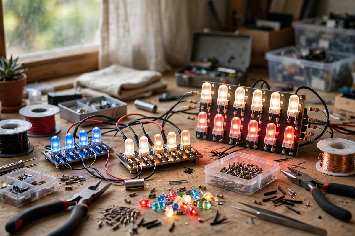
Why LEDs Need Current Limiting
An LED's current-voltage relationship is exponential: a small voltage increase past the forward voltage produces a huge current increase. Connected directly to a voltage supply, minor supply variations or temperature changes cause runaway current: the LED heats, its forward voltage drops with temperature, current increases further, and thermal runaway destroys it. The resistor linearizes the circuit: it drops the excess voltage and its resistance dominates the current determination, stabilizing the LED against its own exponential nature.
In arrays, the need multiplies. Parallel LEDs without individual limiting share current unevenly: the LED with the lowest forward voltage hogs current, heats, drops further, and hogs more, until it fails and the cascade moves to the next. Every parallel branch needs its own current limiting; a single shared resistor for parallel LEDs is a failure design.
The Basic Calculation
For a series string of LEDs with one resistor: subtract the total LED forward voltage (number of LEDs times the per-LED forward voltage) from the supply voltage to get the voltage the resistor must drop; divide by the desired current to get the resistance (Ohm's law: R = V / I). Then compute the resistor's power dissipation (P = V × I) and select a resistor rated for at least twice that, because resistors running near their rating run hot and drift.
Example in principle: a 12V supply driving three LEDs at 3V forward voltage each leaves 3V for the resistor; at 20mA desired current, the resistor is 3V / 0.02A = 150 ohms, dissipating 3V × 0.02A = 0.06W, so a standard quarter-watt resistor serves with comfortable margin. The arithmetic is always this shape; only the numbers change.
Series-Parallel Array Design
Large arrays combine series strings in parallel: each string gets its own resistor, and the strings share the supply. Size each string to use the supply voltage efficiently: the number of LEDs per string should leave enough voltage for the resistor to regulate (at least a volt or two; less headroom means poorer current stability), but not so much that the resistor wastes excessive power as heat.
- Keep strings identical: same LED count, same LED type, same resistor value, for uniform brightness.
- Calculate per string, then sum the string currents for the supply's total current requirement.
- Derate resistor power generously; hot resistors in enclosed fixtures fail early.
- Verify with measurement; LED forward voltages vary, and the calculated current is approximate until confirmed.
Accounting for Variation
LED forward voltage varies between units, between batches, and with temperature (dropping roughly 2mV per degree Celsius for typical LEDs). Design the resistor for the nominal case but check the extremes: at the lowest expected forward voltage (hot LEDs, low-Vf batch), does the current stay within the LED's rating? At the highest, is the brightness still acceptable? Adequate voltage headroom across the resistor absorbs these variations; marginal headroom turns variation into visible brightness differences or overcurrent.
Supply voltage variation matters equally. An automotive 12V system that swings from 11V to 14.5V needs the resistor calculated for the worst case (highest supply voltage for current limiting) with acceptable dimming at the lowest. Unregulated supplies demand conservative design.
When Resistors Are Not Enough
Resistor limiting wastes the dropped voltage as heat, which becomes significant in large arrays or tight headroom designs. For efficiency-critical applications, constant-current LED drivers replace the resistors: they regulate current actively regardless of voltage variations, wasting minimal power. The calculation above remains the essential understanding, driver or not, because it describes what the driver is doing and what happens when it is absent.
Thermal management completes the design: LEDs at their rated current still generate heat, and the array's lifetime depends on keeping junction temperatures down. The resistor calculation sets the electrical operating point; heatsinking and airflow set the thermal one. Both must be right for the array to last.
Subtract the LED drops, divide by the current, double the power rating, resistor per string, and verify by measurement. The current-limiting resistor is the humblest component in the array and the one standing between the LEDs and thermal runaway; calculate it carefully.
Related Guides
- Constant Current LED Driver Ripple Control: LEDs are current-driven devices: their brightness follows current, and their forward voltage shifts with temperature, which means a voltage source
- Constant Voltage Driver Voltage Drop Calculations: Low-voltage lighting runs, LED strips, landscape circuits, and cabinet lights all share a quiet failure mode: the far end of the run glows dimmer and
- Low Voltage Drop Sizing on Long LED Tape Runs: LED tape looks simple until the far end of a long run glows dimmer and yellower than the start. That fade is voltage drop: the thin copper traces in
- Selecting Wire Gauges to Prevent Low Voltage DC Drops: Low-voltage DC circuits, 12V and 24V lighting, automotive accessories, solar setups, are brutally sensitive to voltage drop in a way that