
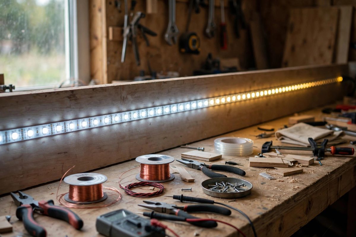
LED tape looks simple until the far end of a long run glows dimmer and yellower than the start. That fade is voltage drop: the thin copper traces in the tape have real resistance, and current flowing through that resistance drops voltage along the length. The LEDs at the far end receive less voltage, draw less current, and emit less light, with color shift because LED color depends on current. Sizing a long run for low voltage drop is an electrical design exercise, and it starts with accepting that the tape's own conductors are the limiting factor.
Why Tape Traces Drop Voltage
LED tape carries power on thin copper foil traces, often just an ounce or two of copper, running the full length of the strip. Resistance accumulates with length: each additional foot adds its trace resistance in series, and the current for all downstream LEDs flows through the upstream trace. This creates a compounding effect: the first section carries the current for the entire run and drops the most voltage, while each subsequent section carries less current but adds its drop to the total. The result is a voltage gradient along the tape, highest at the feed end, lowest at the far end. LEDs are current-driven devices with a steep voltage-current relationship, so even a modest voltage drop produces a visible brightness difference, and white LEDs shift color noticeably because the phosphor balance changes with current.
Calculating the Drop
The drop follows Ohm's law applied to the tape's resistance per unit length. Estimate the total current from the tape's power rating and the supply voltage, then multiply by the trace resistance over the run length, remembering that both the positive and negative traces contribute, so the round-trip length counts. The practical threshold: keep the total drop under roughly 5 to 10 percent of the supply voltage for acceptable uniformity, tighter for critical architectural lighting. Higher supply voltages help enormously: at 24V, the same power needs half the current of 12V, and since drop is proportional to current, the voltage drop halves too, while the percentage drop quarters because the supply voltage doubled. This is why long runs favor 24V tape: the physics is twice as forgiving before you do anything else. Run the numbers before buying tape; the calculation takes minutes and prevents the most common LED tape disappointment.
Feed Strategies: Both Ends and Middle
How you feed power matters as much as the tape's resistance. Feeding from one end only gives the maximum drop: the full current traverses the full length. Feeding from both ends halves the worst-case path: the middle of the run becomes the lowest-voltage point, fed from both sides, and the maximum drop is roughly a quarter of the single-feed case. Feeding from the middle, or at multiple points along the run, reduces the drop further: each feed point supplies only its local section. The professional approach for long runs is a parallel feeder: run heavier-gauge wire alongside the tape and tap power into the tape every few feet. The heavy wire has negligible drop, so each tape section sees nearly full supply voltage. This is more wiring work, but it is the correct solution for runs where uniformity matters, and it is far cheaper than replacing a disappointing installation.
Wire Gauge for Feeders
The feeder wire must be sized for the current it carries with minimal drop of its own. Size it like any low-voltage power run: calculate the current per feeder segment, choose a gauge whose resistance over the segment length keeps the drop small, and remember that low-voltage systems are unforgiving because the supply voltage is small to begin with. A drop of one volt is trivial on a 120V circuit and devastating on a 12V one. Keep feeder runs as short as practical by placing the power supply centrally rather than at one end. Use proper connections at each tap point: soldered joints or quality connectors, because a resistive connection in the feeder reintroduces the very drop you are eliminating. And fuse the feeder appropriately: heavy wire carrying real current needs overcurrent protection just like any power wiring.
Power Supply Placement and Capacity
Place power supplies to minimize feeder length, which usually means centrally located or distributed along the run rather than piled at one end. Size the supply with headroom: running a supply at its absolute maximum rating shortens its life and leaves no margin for the inrush and thermal realities of real installations. A supply loaded to roughly 80 percent of its rating runs cooler and lasts longer. For very long runs, multiple smaller supplies distributed along the length often beat one large central supply, because each supply's feeder runs stay short. Keep supplies ventilated and accessible: LED drivers generate heat, and a supply cooked inside a sealed cavity fails early. Plan the supply locations during layout, not after the tape is up, because retrofitting power distribution into a finished installation is where budgets go to die.
Voltage drop on LED tape is physics, not a product defect: thin traces, real current, Ohm's law. Calculate the drop, favor 24V for long runs, feed from both ends or via parallel feeders, size the wire for the low voltage, and place supplies centrally. The far end will match the near end, which is the entire goal.
Related Guides
- Constant Voltage Driver Voltage Drop Calculations: Low-voltage lighting runs, LED strips, landscape circuits, and cabinet lights all share a quiet failure mode: the far end of the run glows dimmer and
- Selecting Wire Gauges to Prevent Low Voltage DC Drops: Low-voltage DC circuits, 12V and 24V lighting, automotive accessories, solar setups, are brutally sensitive to voltage drop in a way that
- Constant Current LED Driver Ripple Control: LEDs are current-driven devices: their brightness follows current, and their forward voltage shifts with temperature, which means a voltage source
- Current-Limiting Resistor Calculations for Arrays: LED arrays, multiple light-emitting diodes wired together for task lighting, accent lighting, or indicators, need current limiting: LEDs are