
A solenoid is an inductor, and inductors fight changes in current. When the Arduino switches a solenoid off, the collapsing magnetic field drives a voltage spike backward into the circuit, often tens or hundreds of volts, far beyond what the switching transistor or the Arduino can survive. A flyback diode gives that spike a safe path to dissipate. Sizing the diode correctly is a small task that stands between a working project and a dead microcontroller.
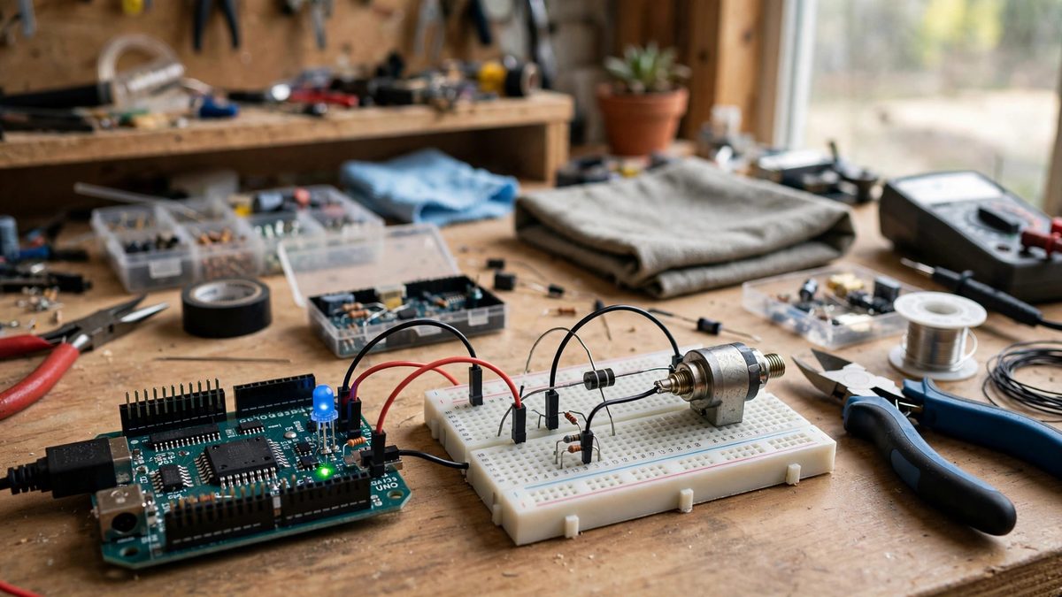
Why the spike happens
Current through an inductor cannot change instantly; the magnetic field stores energy, and when the circuit opens, that energy has to go somewhere. It goes into voltage: the inductor generates whatever voltage is necessary to keep the current flowing momentarily, which means a large negative spike across the switching transistor. Without a diode, that spike appears across the transistor's terminals, and most small transistors and MOSFETs die at a fraction of the voltage a solenoid can produce.
The Arduino itself is usually not the first casualty, since the transistor sits between it and the solenoid, but the spike couples through ground and supply rails too, causing resets, erratic behavior, and eventual damage. The diode protects the whole circuit, not just the switch.
How the flyback diode works
The diode is placed in parallel with the solenoid coil, reverse-biased during normal operation so it conducts nothing while the solenoid is energized. When the switch opens and the coil voltage reverses, the diode becomes forward-biased and conducts, circulating the coil's current through the diode in a decaying loop until the magnetic energy dissipates as heat. The spike is clamped to roughly the diode's forward voltage drop above the supply rail, well within safe limits.
Placement matters: the diode must be electrically close to the coil, with short leads, because the loop it forms with the coil carries the full spike current. A diode at the far end of long wires lets the spike develop voltage across the wire inductance before the diode can clamp it. Solder it right at the solenoid terminals when possible.
Sizing the diode: voltage and current ratings
Two ratings matter. The reverse voltage rating must exceed the supply voltage with comfortable margin; for a 12V solenoid circuit, a diode rated for 50V or more is appropriate, since the diode sees the full supply voltage in reverse during normal operation. The forward current rating must handle the solenoid's operating current, because at the instant of switch-off the diode carries the full coil current before it decays.
In practice, the common 1N400x series covers most small Arduino solenoids: rated for 1A continuous and 50 to 1000V reverse depending on the variant, which handles typical 12V solenoids drawing well under an amp. For larger solenoids drawing an amp or more, step up to a 1N540x (3A) or a Schottky diode of appropriate rating. Schottky diodes switch faster and drop less voltage, which clamps the spike tighter and dissipates the energy quicker, at the cost of lower reverse voltage ratings.
The release-time tradeoff
The diode slows the solenoid's release slightly, because the circulating current keeps the magnetic field alive briefly after switch-off. For most automation tasks this delay, measured in milliseconds, is irrelevant. For high-speed switching, where the solenoid must release as fast as it engages, a plain diode may be too slow; a Zener diode in series with the flyback diode, or a resistor in series, lets the spike rise to a controlled higher voltage and dissipates the energy faster, at the cost of more stress on the transistor. Size the transistor's voltage rating to accommodate whichever approach you choose.
Wiring it into the Arduino circuit
The standard low-side switch arrangement: solenoid between the supply rail and the transistor's drain or collector, transistor source or emitter to ground, Arduino pin driving the gate or base through a resistor. The flyback diode goes across the solenoid with its cathode (striped end) toward the supply rail and anode toward the transistor. Double-check the polarity before powering up; a reversed diode shorts the supply through the transistor the moment it switches on.
Test with a meter before trusting it: energize the solenoid, switch it off, and confirm the circuit survives repeated cycling with no resets or heat at the transistor. The diode is a fifty-cent part doing a critical job; verify it is doing it.
Diode across the coil, cathode to supply, rated above the coil current and well above the supply voltage, mounted at the solenoid. That is the whole circuit, and it is the difference between reliable automation and mysterious dead boards.
Related Guides
- Flyback Diode Sizing on Solenoid Valve Drivers: Every solenoid valve is an inductor, and every inductor fights changes in current. When an Arduino-driven transistor switches a solenoid off, the
- Optocoupler Relay Isolation for Arduino: The moment an Arduino project grows up from blinking LEDs to switching lamps, pumps, or heaters, it needs relays, and relays need isolation. An
- Arduino Blink: Your First Electronics Project: Welcome to the World of Arduino! If you're brand new to electronics and microcontrollers, the "Blink" sketch is your "Hello World" moment. This
- Solid State Relay Snubber Design for Arduino: A solid state relay lets an Arduino switch mains-powered loads with no moving parts, but switching an inductive load, a motor, a transformer, a
- Optocoupler Switching Delays in High-Speed I/O: Optocouplers isolate circuits by transmitting signals as light: an LED shines on a phototransistor across a gap, so the two sides share no electrical