
Every solenoid valve is an inductor, and every inductor fights changes in current. When an Arduino-driven transistor switches a solenoid off, the collapsing magnetic field generates a voltage spike that can destroy the transistor, reset the microcontroller, or worse. The flyback diode is the standard defense, and sizing it correctly is the difference between a reliable automation and a flaky one.
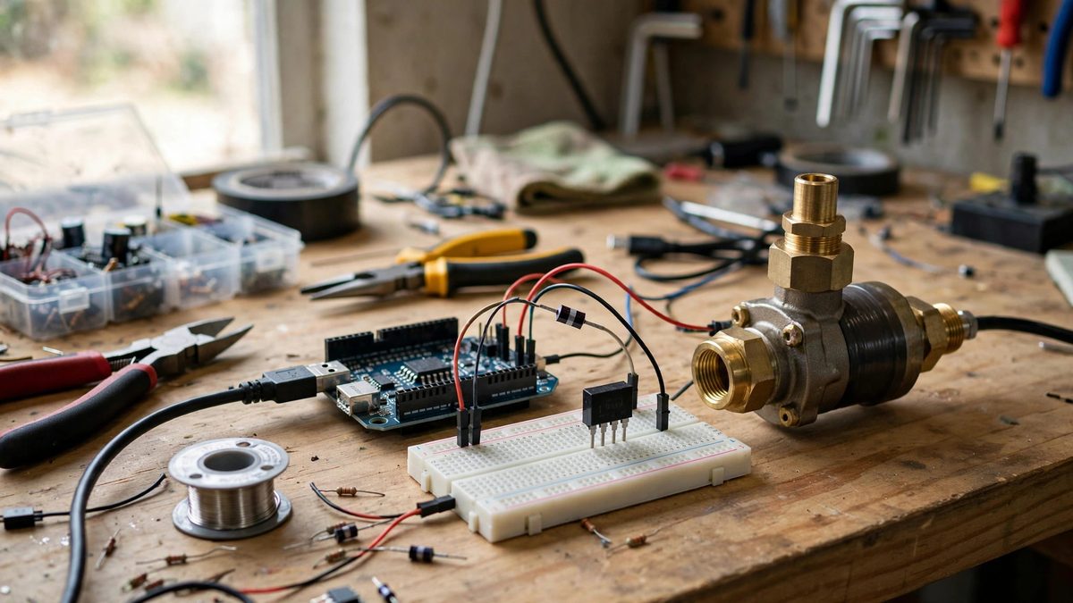
Why the Spike Happens
An inductor's current cannot change instantaneously; the magnetic field stores energy, and interrupting the current forces that energy somewhere. When the driving transistor turns off, the solenoid's inductance tries to keep the current flowing, generating a voltage spike across the coil that can reach many times the supply voltage, with the polarity reversed from normal operation. Without protection, this spike appears across the transistor, exceeding its breakdown voltage and punching through the junction. Even if the transistor survives, the spike couples into the power rails and ground, causing the Arduino to reset or behave erratically. This is not a rare edge case; it happens on every single switching cycle of an unprotected solenoid. The diode gives the spike current a safe path.
How the Flyback Diode Works
The diode connects across the solenoid coil in reverse bias during normal operation: cathode to the positive supply side, anode to the transistor side. It conducts nothing while the solenoid is energized. The instant the transistor switches off and the coil voltage reverses, the diode becomes forward biased and clamps the spike to about a diode drop above the supply rail. The coil's stored energy then circulates through the diode and the coil's own resistance, decaying as heat over a few milliseconds. The transistor never sees more than the supply voltage plus the diode drop. The solenoid releases slightly more slowly than it would without the diode, since the current decays gradually rather than being forced to zero; for most valve applications this delay of a few milliseconds is irrelevant, but it matters in high-speed switching.
Sizing the Diode
The diode must handle the solenoid's full operating current, since at the moment of switch-off the coil current equals the steady-state current and the diode carries all of it. Choose a diode with a continuous current rating comfortably above the solenoid's draw; a common rule sizes the diode for at least the full coil current, with margin. The voltage rating must exceed the supply voltage with headroom, though the diode never sees high voltage in this circuit; the rating is about robustness, not the spike. Speed matters: a standard rectifier diode is adequate for slow-switching valves, but for PWM-driven solenoids use a fast or Schottky diode, since a slow diode lets the spike rise before clamping. The classic general-purpose choice for small solenoids is a 1N400x series diode, which handles an amp of current; larger solenoids want correspondingly larger diodes. When in doubt, oversize the diode; it costs pennies.
Placement and Wiring
Mount the diode as close to the solenoid coil as possible, ideally right at the valve's terminals. Long wires between the diode and the coil have inductance of their own, which lets the spike develop before the diode can clamp it; the protection degrades with distance. Keep the loop area small: run the diode leads directly across the coil terminals with short, direct wiring. On a PCB, place the diode adjacent to the driver transistor and the coil connector, with wide traces for the recirculation path. Observe the polarity with extreme care; a diode installed backwards shorts the power supply through the transistor the moment it switches on, which is a more dramatic failure than the spike it was meant to prevent. Double-check with a meter before powering up.
Verifying the Protection
Test with an oscilloscope on the transistor's collector or drain if you have one: without the diode you will see a large negative spike at switch-off, and with the diode the waveform clamps cleanly near the supply rail. Without a scope, watch for symptoms: an Arduino that resets when the valve switches, or transistors that fail after some operating time, both point to inadequate spike suppression. Also verify the release timing if the application is speed-critical; if the diode slows the valve too much, a Zener diode in series with the flyback diode (or a resistor) lets the spike rise to a controlled higher voltage, dumping the energy faster. But for the vast majority of Arduino solenoid projects, a correctly sized diode at the coil terminals makes the problem disappear permanently.
The flyback diode is non-negotiable on solenoid drivers: size it for the full coil current, use fast types for PWM, mount it at the coil terminals with correct polarity, and verify the clamping. One diode, placed right, protects the whole circuit.
Related Guides
- Flyback Diode Sizing for Inductive Arduino Solenoids: A solenoid is an inductor, and inductors fight changes in current. When the Arduino switches a solenoid off, the collapsing magnetic field drives a
- Arduino Blink: Your First Electronics Project: Welcome to the World of Arduino! If you're brand new to electronics and microcontrollers, the "Blink" sketch is your "Hello World" moment. This
- Optocoupler Relay Isolation for Arduino: The moment an Arduino project grows up from blinking LEDs to switching lamps, pumps, or heaters, it needs relays, and relays need isolation. An
- Solid State Relay Snubber Design for Arduino: A solid state relay lets an Arduino switch mains-powered loads with no moving parts, but switching an inductive load, a motor, a transformer, a
- Optocoupler Switching Delays in High-Speed I/O: Optocouplers isolate circuits by transmitting signals as light: an LED shines on a phototransistor across a gap, so the two sides share no electrical