
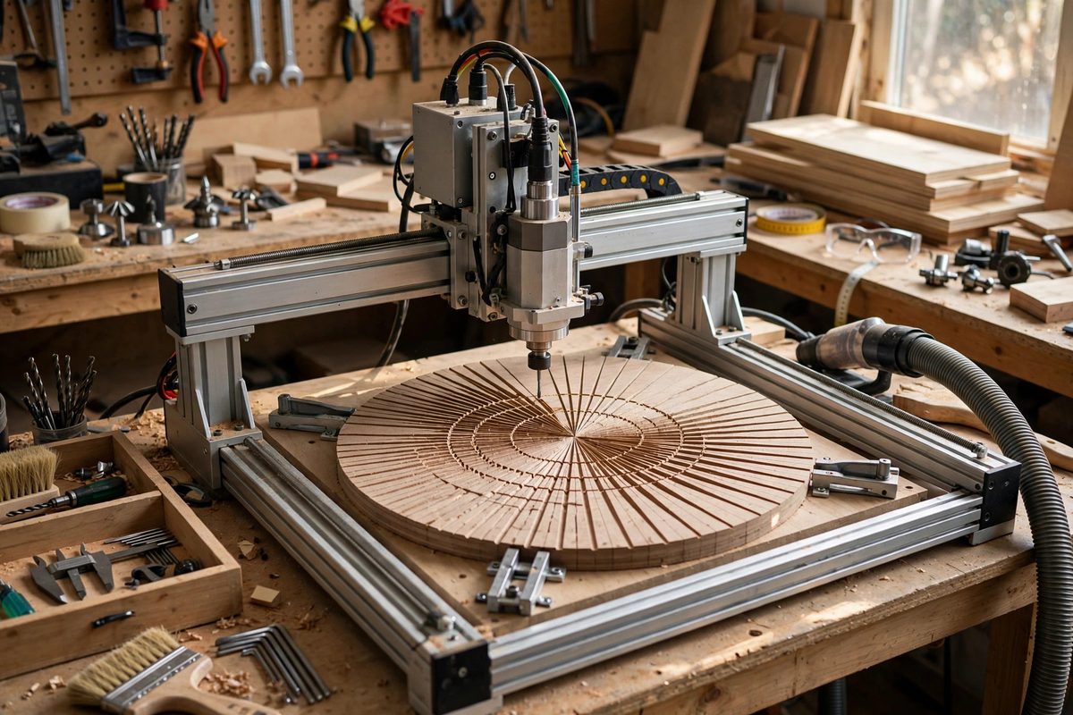
Most CNC work lives in Cartesian coordinates: X left-right, Y front-back, and the machine interpolates straight lines and arcs between points. But some work is naturally polar: radial patterns, circular arrays, spiral toolpaths, anything organized around a center. Polar coordinate interpolation, commanding positions as radius and angle instead of X and Y, matches the machine's motion to the part's geometry. Grbl, the ubiquitous open-source motion controller, does not speak polar natively, which means polar work requires understanding what Grbl does and bridging the gap deliberately.
What Polar Interpolation Means
In polar coordinates, a position is defined by its distance from an origin (radius) and its angular position around that origin (angle). A circular toolpath at constant radius becomes trivially simple: hold radius constant, sweep the angle. A spiral is equally natural: advance the radius proportionally with the angle. In Cartesian coordinates, both require computing sine and cosine at every point, which is why CAM software normally handles the conversion and Grbl never sees the polar form.
True polar interpolation would mean the controller itself accepts radius-angle commands and generates the coordinated axis motion. Industrial controllers sometimes offer this as a feature; Grbl does not. The practical question is therefore how to get polar-organized toolpaths into a Cartesian-only controller without losing the polar advantages.
The Standard Approach: Convert in CAM
The overwhelmingly common solution is to let the CAM software do the conversion: design or generate the toolpath in polar terms (or simply design the polar geometry), and have the CAM postprocessor emit Cartesian G-code with enough resolution that the faceting is invisible. A circle becomes many small G1 linear moves or a G2/G3 arc command; a spiral becomes a polyline with fine segmentation. Grbl executes the Cartesian moves perfectly, never knowing the design was polar.
The key parameter is segmentation tolerance: how finely the curves are divided. Too coarse and the circle shows flats; too fine and the G-code file bloats, potentially overwhelming Grbl's serial buffer on long programs. A tolerance around a hundredth of a millimeter (or finer for small detailed work) is a solid starting point, adjusted to the part's scale.
Rotary Axis as Physical Polar
Grbl setups with a rotary axis (typically the A axis) achieve a physical form of polar interpolation: the rotary axis provides the angle directly, and the linear axis provides the radius. A toolpath that is genuinely polar in the machine's kinematics, such as engraving around a cylinder or cutting a spiral on a disc mounted to the rotary axis, programs naturally as coordinated A and X moves. This is polar interpolation in the most literal sense: the machine's axes are the polar coordinates.
- Calibrate steps-per-degree on the rotary axis carefully; angular error multiplies by radius.
- Account for the rotary axis's backlash; approach angular positions consistently from one direction.
- Set the rotary axis's speeds in degrees per minute; Grbl handles the unit conversion if configured.
- Test with air cuts first; rotary programming errors produce dramatic wrong motion.
Manual Polar Programming Techniques
For simple polar patterns, hand-written G-code with a calculator or spreadsheet does the job. Compute the Cartesian coordinates of each polar point (X = R·cos θ, Y = R·sin θ, relative to the chosen origin), and emit the moves. Circular arrays of holes, radial slots, and bolt circles are all straightforward: the math is simple trigonometry, and a spreadsheet generates dozens of points in seconds.
Set the work origin at the polar center to keep the math clean. If the polar pattern is not at the machine's work zero, use a work coordinate offset (G54 and friends) to place the origin at the pattern's center, do the polar math in local coordinates, and let the offset handle the translation. This separation keeps the trigonometry simple and the setup flexible.
Arc Commands as Polar Shortcuts
Grbl's G2/G3 arc commands are a limited form of polar thinking built into the Cartesian system: they describe circular motion around a center point, which is exactly the constant-radius polar move. For circular toolpaths, arcs are more compact and smoother than segmented lines, and Grbl executes them with true arc interpolation. Use arcs wherever the geometry is genuinely circular; reserve segmented polylines for spirals and non-circular polar curves.
The combination covers nearly all polar work on Grbl: arcs for the circular elements, fine segmentation for the rest, rotary axis where the machine has one. Polar interpolation as a controller feature would be convenient, but the Cartesian workarounds, done thoughtfully, produce identical motion at the tool.
Design polar, post Cartesian, segment finely, and use arcs where they fit. Grbl does not need to speak polar for your parts to come out round; it just needs good coordinates, and those you can provide.
Related Guides
- Custom Arc Acceleration Smoothing Rules: G-code arcs (G2 and G3) look smooth on screen but can make a machine stutter, dwell, or gouge if the controller and the motion planner disagree about
- Subprogram Looping and Macro Calls in Fanuc G-Code: Repetitive machining, drilling a bolt circle, milling a pocket pattern, engraving a row of labels, does not need repetitive code. Fanuc G-code
- Modal Group Interactions in Fanuc Turning Cycles: Fanuc canned cycles for turning, the G70 through G76 family, are powerful shortcuts, but they interact with modal G-code groups in ways that surprise
- G91 Incremental Subroutines for Repetitive Milling: Repetitive milling, a row of identical pockets, a grid of holes, a pattern of slots, is where hand-written G-code earns its keep, and G91 incremental