
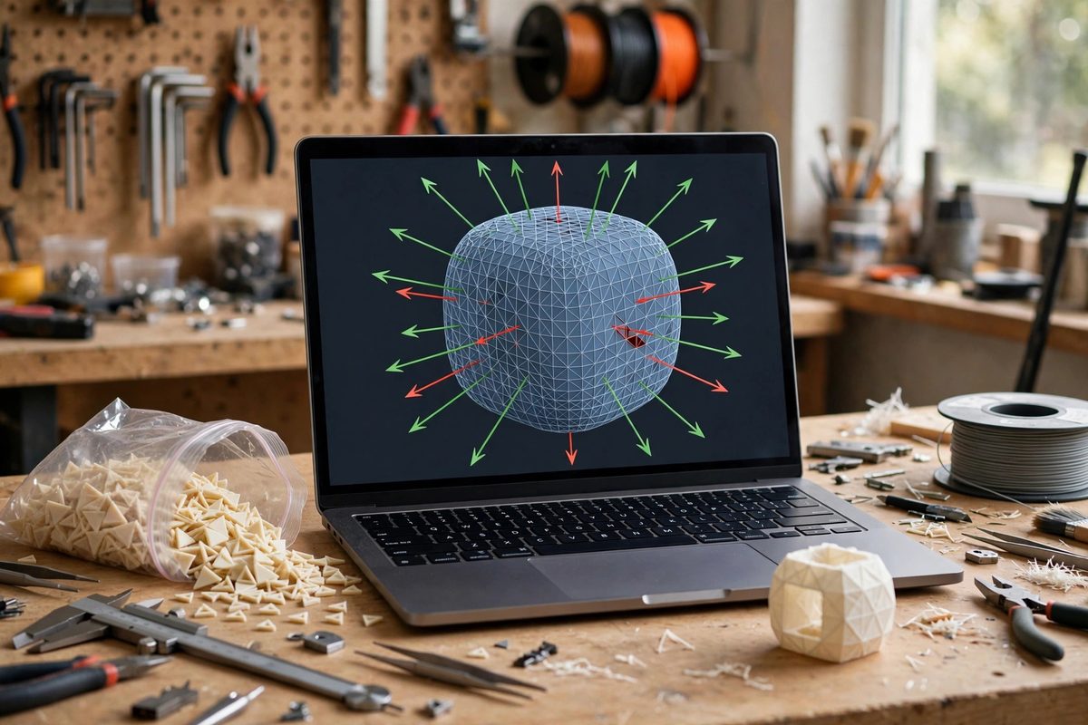
An STL file is a bag of triangles, and each triangle has a normal, an arrow declaring which side is "outside." When some of those arrows point inward, the mesh has inverted normals, and slicers get confused about what is solid and what is air. The symptoms are familiar: missing walls in the preview, sliced layers with holes, or a print that looks fine in the viewer but fails on the machine. Inverted normals are one of the most common reasons a CAD model that looks perfect on screen slices badly, and they are fixable once you understand how they happen.
What a Normal Decides
A slicer determines the inside of a part by ray casting or winding rules applied to the triangle normals: roughly, it figures out which regions of each layer are enclosed by outward-facing triangles and fills those. A triangle with an inverted normal tells the slicer that the solid is on the wrong side. A few scattered inverted facets usually get outvoted by their correctly oriented neighbors and cause no visible harm. But a patch of inverted facets, common on a face that was mirrored, flipped, or booleaned, creates a region where the slicer genuinely cannot tell inside from outside. The result is unpredictable: sometimes the region is treated as a void and left hollow, sometimes the slicer heals it arbitrarily and produces geometry you did not design. The insidious part is that the CAD viewport often renders the model fine, because viewport shading and slicing use the normals differently.
How Inversions Happen in CAD
Most inverted normals are born during modeling operations, not during export. Mirroring a body across a plane flips the orientation of every triangle unless the CAD tool corrects it; some tools do, some do not. Boolean operations, especially subtracting a complex shape, can leave fragments with inconsistent orientation along the intersection seams. Importing and repairing geometry from another program often produces mixed orientation where the repair stitched patches in backwards. Scaling by a negative factor, the quick way to mirror, inverts everything. Even simple operations like flipping a face's direction during surface modeling can propagate. The pattern to recognize: inversions cluster around operations that reverse handedness or stitch boundaries. If a print fails near a mirrored feature or a boolean seam, normals are the first suspect.
Detecting the Problem Before Slicing
Check the mesh before it reaches the slicer. Most mesh tools and many CAD programs have a normals display mode that colors back-facing triangles differently, often red, making inverted patches immediately visible. A quicker heuristic: view the model with flat shading and look for faces that render dark or oddly lit compared to their neighbors; inconsistent shading across a smooth surface often marks an orientation flip. Some slicers include a mesh analysis or repair report on import that flags inverted or inconsistent normals explicitly. Make this check part of the export routine for any model that involved mirroring, booleans, or imported geometry. Catching the problem in the mesh tool takes seconds; discovering it in a failed six-hour print takes six hours.
Fixing Orientation
The fix depends on the extent. For scattered individual facets, most mesh repair tools offer a "recalculate" or "unify normals" operation that flips triangles to match the majority orientation of their neighbors; this handles the common case cleanly. For a large coherent patch, such as an entire mirrored half, select the patch and flip it as a group, which is faster and safer than relying on automatic unification across a sharp boundary. When automatic tools fail, the underlying cause is usually a non-manifold edge or a hole nearby: the algorithm cannot decide orientation where the surface is not closed. Fix the topology first, close the holes, resolve the non-manifold edges, then unify normals. After any fix, re-run the detection pass to confirm the mesh is consistently oriented before exporting.
Export Settings That Prevent Recurrence
Some inversions are introduced at export, not in the model. Exporting with inconsistent tolerance settings can cause the tessellator to generate degenerate or flipped triangles along curved surfaces. Keep export tolerances reasonable: too fine a tolerance creates enormous triangle counts without improving orientation, and too coarse creates faceted curves, but neither extreme should flip normals if the source solid is valid. Export from the solid body, not from a surface or mesh representation, whenever the option exists; the solid's topology gives the exporter the information it needs to orient triangles correctly. If your CAD tool offers a "validate" or "check solid" before export, run it: a solid that fails validation often exports with exactly the orientation errors you are trying to avoid. And keep the original CAD file: when a mesh proves unfixable, re-exporting from a corrected solid beats hours of mesh surgery.
Inverted normals are a bookkeeping error, not a design error, which is why they are so frustrating: the model is right and the mesh is wrong. Check orientation after mirrors and booleans, unify before slicing, and fix topology when unification fails. The slicer will thank you with prints that match the screen.
Related Guides
- Repairing Non-Manifold Geometry in Meshes: A mesh is manifold when it describes a watertight solid: every edge is shared by exactly two faces, with a consistent inside and outside
- Healing Degenerate Facets and Self-Intersections: An STL file is just a list of triangles, and not all triangle lists describe a printable solid. Degenerate facets, triangles with zero area, and
- Boundary Loop Normal Alignment on Complex Shells: An STL file describes a 3D model as a mesh of triangles, and each triangle has a normal, the direction its face points. For a closed, printable
- Repairing Flipped Normals and Self-Intersecting Faces: An STL file is just a list of triangles, and the slicer trusts that list completely. When triangles have flipped normals, the slicer thinks the