
A directional Wi-Fi board, a patch antenna or a small array feeding an ESP32 bridge, lives or dies by its RF ground plane. The ground plane is part of the antenna system, not just a power return: its size, shape, and continuity determine the antenna's radiation pattern, its efficiency, and whether the directional gain you designed for actually materializes. Isolating the RF section's ground from the noisy digital ground, while keeping them connected correctly, is the layout discipline that makes these boards work.
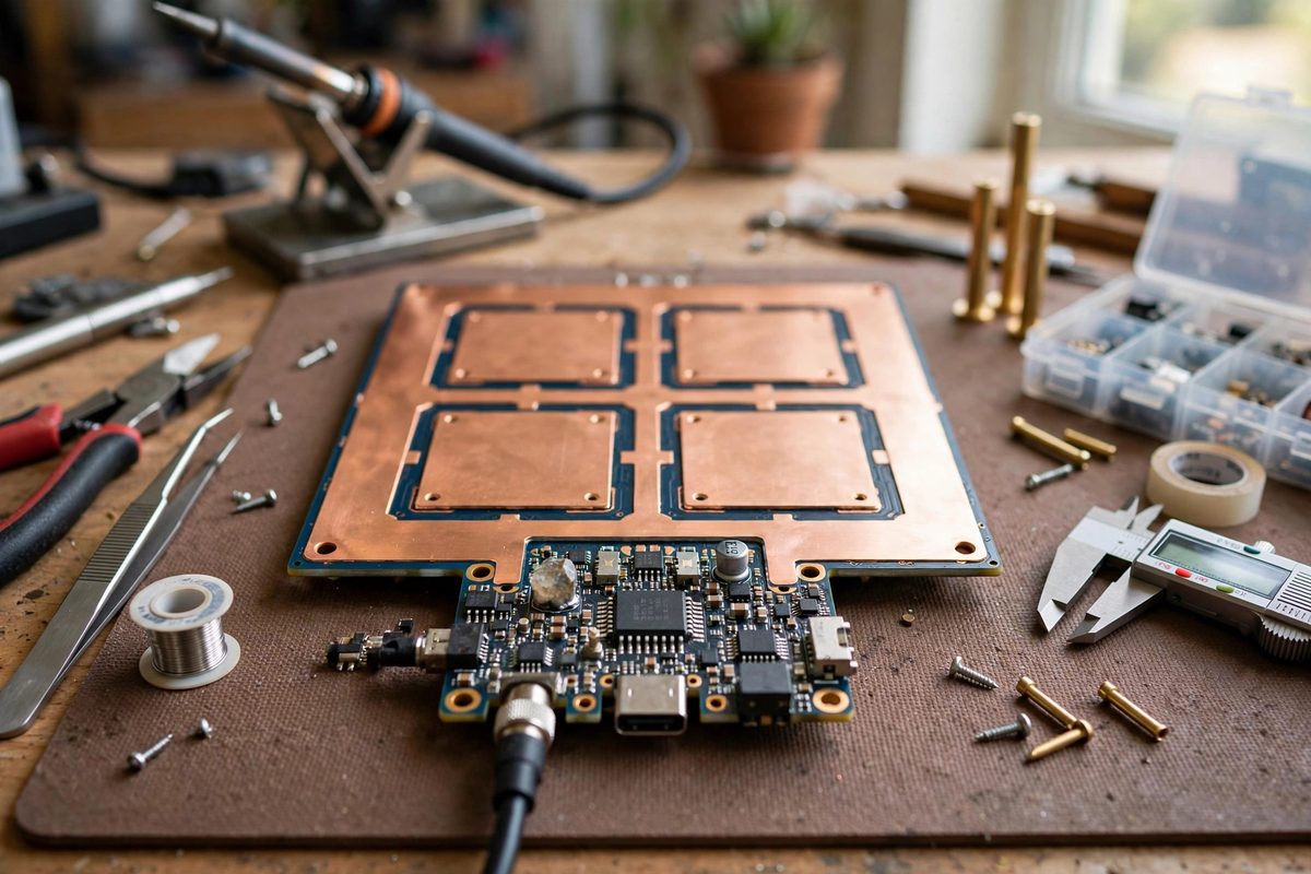
The ground plane as an antenna element
For the common antenna types used on ESP32 bridge boards, the ground plane is the other half of the antenna. A patch antenna radiates between the patch and the ground beneath it; a monopole or PCB trace antenna uses the ground plane as its counterpoise. Change the ground plane's size or shape and you change the antenna's resonant frequency, its impedance, and its pattern. This is why antenna datasheets specify a minimum ground plane size and why deviating from the reference layout degrades performance in ways that look like a bad antenna but are really a bad ground.
Directionality makes this more critical, not less. A directional antenna achieves its gain by shaping where energy goes, and the ground plane is part of that shaping. A ground plane with slots, cuts, or chunks missing under the antenna distorts the pattern, often spraying energy in unintended directions and killing the front-to-back ratio the design was counting on.
Why isolation from digital ground matters
The ESP32's digital circuitry dumps switching noise into its ground: sharp current spikes from the processor, the Wi-Fi radio's own power amplifier pulsing, regulator noise. If the RF ground plane is just a continuation of that noisy ground with no thought given to current paths, the noise couples directly into the antenna system, raising the noise floor and desensitizing the receiver. The symptom is a link that works at short range and falls apart at distance, or throughput that never reaches what the hardware should deliver.
Isolation does not mean disconnection. The RF ground and the digital ground must join at exactly one point, ideally right at the antenna feed or the radio module's ground pins, so that digital return currents cannot flow across the RF ground plane. A single-point connection, sometimes called a star ground, forces the noisy currents to take their own path home instead of wandering through the antenna's reference plane.
Layout practices that preserve the plane
Keep the ground plane under and around the antenna solid and unbroken: no signal traces crossing it, no slots, no mounting holes inside the keep-out region the antenna design specifies. Route digital signals on other layers or around the RF section, never through it. If the board is two-layer, dedicate the bottom layer under the RF section to uninterrupted ground and accept the routing inconvenience elsewhere.
Place decoupling capacitors at the radio module's power pins with short, direct connections to the ground plane, so high-frequency noise has a local path home instead of traveling across the board. Stitch the ground planes of a multilayer board with vias around the RF section's perimeter, forming a fence that contains the RF fields and keeps digital noise out. The via fence is cheap in layout effort and remarkably effective.
Keep-out zones and enclosures
Respect the antenna's keep-out zone in all three dimensions. Metal near the antenna, a battery, a shield can, a mounting bracket, detunes it and distorts the pattern just as surely as a cut in the ground plane. Plastic enclosures are generally fine, but keep metal objects at least the distance the antenna documentation specifies, and remember that the ground plane's own size counts: a board smaller than the recommended ground plane will underperform no matter how clean the layout.
Test the finished board's range and throughput against expectations before deploying it as a bridge. A directional board that performs like an omnidirectional one, or a link budget that comes up short, usually traces back to the ground plane: a slot someone routed through it, a noisy ground connection, or metal too close to the antenna.
The antenna gets the credit, but the ground plane does half the work. Keep it solid, keep it quiet, join it once, and keep metal away, and the directional gain will be there when you need it.
Related Guides
- High-Gain Directional Wi-Fi Bridge Antennas: When an ESP32 project needs to reach across a yard, between buildings, or to the far corner of a property, the stock antenna gives up long before the
- Ground Plane Shielding on ESP32 Microstrip Lines: The ESP32's Wi-Fi and Bluetooth radios live or die by the RF layout, and the microstrip traces carrying 2.4 GHz signals to the antenna are the most
- AP Station Isolation Protocols for ESP32 Mesh: ESP32 mesh networks, where each node relays for the others to extend coverage, often include an access point interface so phones, laptops, or sensors
- NAT Routing Throughput Limits on ESP32 Bridges: Using an ESP32 as a Wi-Fi bridge, relaying traffic between networks with network address translation, is a tempting trick: the chip has Wi-Fi, it