
Selective soldering solders through-hole components on a board that already carries surface-mount parts, using a small, precise solder wave instead of the full-width wave of traditional wave soldering. On mixed-technology boards the flux application and the wave height must be controlled tightly: too little flux or too low a wave and the joints do not form; too much of either and flux contaminates the SMD areas or the wave damages nearby components. Getting both right is the core skill of the process.
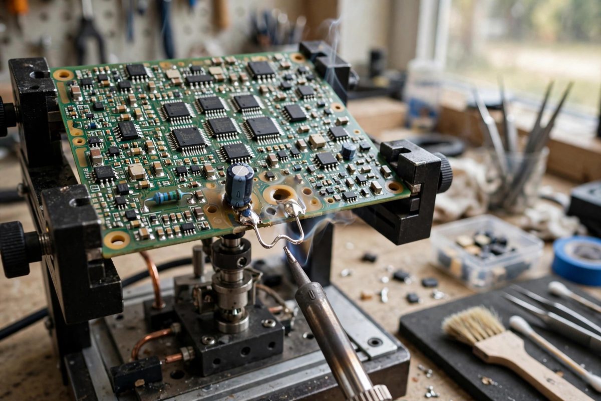
How selective soldering differs from wave soldering
A traditional wave solder machine passes the whole board over a wide standing wave of molten solder, which solders every through-hole joint at once but also exposes every bottom-side component to the wave. Selective soldering replaces the wide wave with a small nozzle, typically a few millimeters to a couple of centimeters across, that solders one joint or one small group of joints at a time while the rest of the board stays clear.
This precision is what makes mixed boards possible: through-hole connectors and large components get soldered after the SMD reflow, without subjecting the already-placed surface-mount parts to another full thermal cycle. But the small wave has less thermal mass than a full wave, so the process window, flux amount, preheat, wave height, contact time, is narrower and must be dialed in per board.
Flux application: amount and placement
Flux prepares the joint surfaces by removing oxides so the solder can wet. In selective soldering it is applied by spray, jet, or drop-jet fluxer, targeted at the through-hole pads and leads. The amount must be enough to fully activate the joint surfaces but not so much that excess flux spreads onto nearby SMD components, seeps under them, or leaves residues that cause leakage or corrosion.
On mixed boards, keep the flux away from the SMD areas. No-clean fluxes reduce the penalty for minor spread, but even no-clean residues in the wrong place can cause problems on high-impedance or RF circuits. Program the fluxer's path to cover the through-hole joints with margin for the wave's footprint but no further, and verify the coverage on the first articles with a visual check under magnification before the solder step.
Wave height: the critical dimension
The solder wave height determines how far up the lead the solder climbs and how much thermal energy the joint receives. Set the wave too low and the solder does not reach the top of the pad, producing incomplete joints with poor fillets on the component side. Set it too high and the wave contacts nearby SMD components, masks, or the board areas that must stay solder-free, potentially bridging, tombstoning small parts, or thermally damaging heat-sensitive components.
Calibrate the wave height with the actual board and a test run: the wave should kiss the through-hole pads and wet up the leads without touching anything else. Because boards vary in thickness and warp slightly, verify the height across the whole board, not just at one point. Adjustable Z-axis control on the solder nozzle lets the program vary the height joint by joint, which is the right approach when tall and short components share the board.
Contact time and drag technique
The nozzle can solder in point mode, dwelling under a single joint, or in drag mode, moving steadily along a row of pins. Drag soldering is faster for connectors and pin headers; the drag speed sets the contact time per joint. Too fast and the joints are cold; too slow and the board soaks excess heat, nearby SMD parts reflow or shift, and the solder can bridge between pins.
Preheat the board before soldering so the wave's limited thermal mass is not fighting a cold board. The preheat brings the whole assembly near soldering temperature, letting the small wave finish the job quickly with minimal contact time. Monitor the board temperature: insufficient preheat is the most common cause of poor selective joints, and it masquerades as a wave height or flux problem.
Inspection and process control
Inspect the first articles thoroughly: fillet shape and wetting on both sides of the board, absence of bridging, no disturbance to nearby SMD parts, and flux residue within acceptable limits. Cross-section a sample joint if the product's reliability demands it; the internal fillet tells the truth about wetting that the surface only hints at.
Log the flux amount, wave height, drag speed, and preheat profile that produced good joints, and re-verify whenever the board revision, component mix, or solder alloy changes. Selective soldering is a precise process with a narrow window; the logbook is what keeps it in the window from run to run.
Target the flux, set the wave to kiss the joints and nothing else, preheat adequately, and inspect the first articles like they matter, because they define every board after them.
Related Guides
- Selective Solder Drag Speeds on Dual-In-Line Leads: Drag soldering a row of dual-in-line leads looks like a magic trick the first time you see it done well. A grooved tip carrying a small reservoir of
- Solder Mask Dam Thickness to Prevent Bridging: Between two adjacent surface-mount pads, a thin wall of solder mask, the dam, keeps molten solder from flowing across the gap and shorting the pads
- Copper Land Pad Widths for Hand Solder Clearances: Hand soldering is more forgiving than reflow in some ways and less in others: the iron can reach places the oven cannot, but the human hand needs
- Thermal Relief Spoke Sizing on Power Planes: Thermal reliefs are the compromise between two enemies: the soldering iron, which needs the joint hot, and the power plane, which wants to wick that