
Input shaping cancels the vibrations that cause ringing and ghosting in 3D prints, but it can only cancel what it can measure. The accelerometer that measures the toolhead's resonant frequencies has to be mounted rigidly, in the right orientation, and as close to the moving mass as practical. A sloppy mount measures the mount's own flexing instead of the toolhead's motion, and the resulting input shaper tuning compensates for a vibration that does not exist while ignoring the one that does.
What the accelerometer is actually measuring
When the toolhead changes direction, the printer's frame and motion system ring at their natural frequencies, like a tuning fork. Those vibrations show up in the print as ripples near sharp corners and fine details. Input shaping works by measuring those frequencies with an accelerometer during fast test moves, then adjusting the motion commands to avoid exciting them.
The measurement has to reflect the toolhead's true motion. If the accelerometer is mounted on a flexible bracket, the bracket adds its own resonance to the reading, and the shaper ends up tuned to the bracket. If the sensor rattles or shifts during the test moves, the data is garbage. Rigidity of the mount is not a nicety; it is the precondition for the whole technique.
Mounting location and orientation
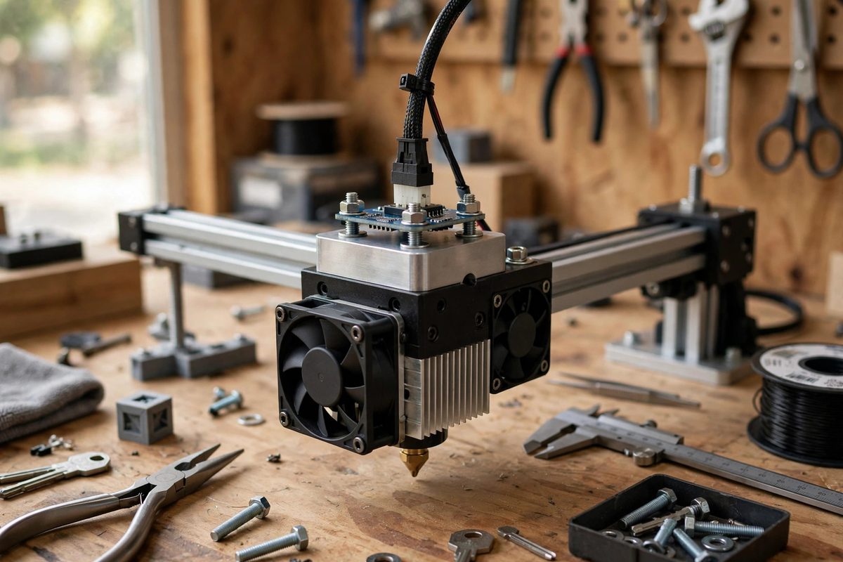
Mount the accelerometer directly on the toolhead, on the same rigid structure that carries the hotend, and orient its axes to match the printer's axes: the sensor's X axis aligned with the printer's X, and so on. Most input shaping setups measure X and Y separately, and a sensor rotated relative to the printer's axes mixes the two measurements, producing a shaper tuning that is wrong for both.
Keep the sensor close to the center of the moving mass rather than out on a extremity. The toolhead rotates slightly as well as translating during fast moves, and a sensor mounted far from the center picks up rotational motion mixed into the translation reading. Centered mounting keeps the measurement clean.
Attachment methods that stay rigid
Screws into existing toolhead mounting holes are the gold standard: metal on metal, torqued snug, no compliance. Many toolheads have spare mounting points or fan screws that can double as accelerometer mounts with a small printed adapter. If an adapter is needed, print it in a rigid material with high infill and keep it compact; a long, thin adapter is a tuning fork that will corrupt the measurement.
Avoid double-sided tape, zip ties, and friction fits for the measurement mount. They are fine for a quick sanity check but not for the calibration run that sets the shaper values, because they all allow micro-movement that shows up as noise or false resonances in the data. The ten minutes spent making a proper screw mount pays for itself in the quality of the tuning.
Running the measurement moves
With the sensor mounted, the firmware runs a series of rapid back-and-forth moves while recording acceleration data. Clear the build plate and make sure nothing can collide during these moves; they are faster and longer than normal printing moves. Keep hands clear and stay near the emergency stop, since a loose mount or a wiring snag during a resonance test can turn violent quickly.
Run the measurement for each axis the shaper will compensate, and check the resulting frequency graphs before accepting the tuning. A clean measurement shows one or two clear resonant peaks per axis. A graph full of jagged noise usually means the mount moved during the test; fix the mount and re-run rather than accepting bad data.
Wiring and cable management
The accelerometer's cable must not tug on the sensor or restrict the toolhead's motion during the test moves. Route it with enough slack and secure it so it moves with the toolhead without pulling. A cable that goes taut mid-test yanks the sensor and spikes the data. After calibration, the sensor can usually be removed; input shaping uses the measured values, not live data, so the accelerometer does not need to stay on the printer.
Rigid mount, correct orientation, centered placement, clean cable routing, and a skeptical look at the data. The shaper is only as good as the measurement, and the measurement is only as good as the mount.
Related Guides
- Tuning Input Shaper Frequencies via Accelerometer: Input shaping cancels the vibrations that cause ringing and ghosting on 3D prints, but it only works when the shaper is tuned to the printer's actual
- CoreXY Belt Tension Tuning for Print Speed: On a CoreXY printer, the belts do more than move the print head. They are the motion system. Two belts working together position the toolhead on
- Stepper Motor Damping for CoreXY Resonance Drops: CoreXY printers are fast because both motors work together to move the toolhead, but that same coupled motion makes them resonance-prone: the long
- Dual Gear Extruder Tension Tuning for Flex TPU: Flexible TPU filament is the 3D printing material that behaves like a wet noodle: it buckles, binds, and jams in extruders designed for rigid