
Many classic consoles generate beautiful RGB video internally and then bury it under noisy, compromised output circuitry before it ever reaches the screen. An RGB bypass amp taps the clean RGB signals directly from the video chip and amplifies them properly, bypassing the stock circuit's noise and delivering the sharp, vivid image the console was always capable of. It is one of the most transformative mods in retro gaming: the same console, the same games, a visibly superior picture. The "low noise" part is not marketing; it is the entire design goal, achieved through careful grounding and construction.
Why stock RGB is noisy
Console manufacturers designed their video output stages for composite video on CRT televisions, where noise and softness were invisible. The RGB signals inside the console often pass through undersized coupling, share ground paths with noisy digital circuitry, or get attenuated and then amplified by marginal transistor stages. The result on a modern display or a quality CRT monitor is jailbars (vertical stripes from digital interference), checkerboard patterns, hum bars, and washed-out colors. A bypass amp solves this architecturally: it picks up the RGB signals at their cleanest point, usually right at the video encoder chip's output pins, and routes them through a short, dedicated, properly grounded amplifier to the output connector. The noisy stock path is simply left unused. The improvement is not subtle; it is the difference between a compromised signal and the console's true capability.
Choosing and placing the amp
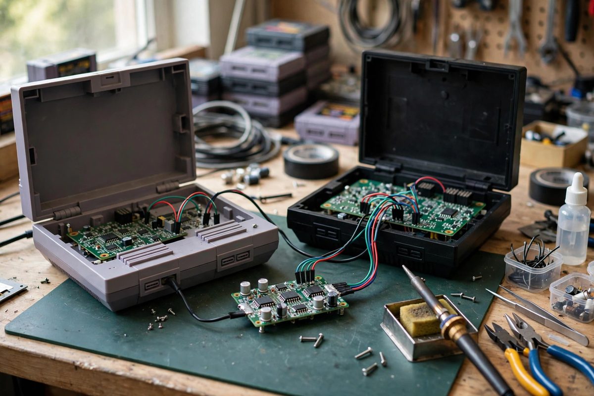
Bypass amps are small PCBs designed per console, since each console's video chip pinout and signal levels differ. Get the board designed for your exact console revision, because revisions change pinouts and a wrong board is worse than none. Placement matters for noise: mount the amp as close to the video chip as practical, keeping the input wires short, since every millimeter of unshielded input wiring is an antenna for the digital noise you are trying to escape. Plan the output routing to the multi-out or new connector before soldering anything; the cleanest amp in the world underperforms if its output wires drape across the power supply. Study the installation guide for your specific board and console, and do a dry fit of the board's position before committing.
Soldering and wiring discipline
The installation is fine-pitch soldering on irreplaceable hardware, so the usual rules apply with extra emphasis. Use a temperature-controlled iron with a fine tip, quality solder, and flux; the video chip pins are small and closely spaced, and bridges here kill video output. Keep input wires short and, where the guide specifies, use shielded wire for the RGB lines with the shield grounded at one end. Power the amp from a clean supply point, usually specified in the guide, and give it solid ground: a short, thick ground wire to a good chassis or ground plane point. Many noise problems blamed on amp design are actually grounding problems in installation. Work methodically, one connection at a time, and verify each with magnification before moving on. Patience at this stage is what separates a clean install from a troubleshooting saga.
Grounding: where low noise comes from
The low-noise performance lives or dies on grounding. The amp's ground must connect to the console's video ground, not just any convenient ground point; digital ground currents from the CPU and other chips create voltage differences across the ground plane, and referencing the amp to the wrong point injects exactly the jailbars you installed the amp to remove. Keep the amp's ground wire short and route it away from noisy digital sections. If the installation guide specifies ferrite beads or specific capacitor placement, follow it; those components filter the high-frequency noise that rides on power and ground. After installation, test on a solid-color screen, which reveals noise patterns that busy game graphics hide. Jailbars, diagonal interference, or hum bars in the test pattern mean the grounding needs rework, not that the amp is defective.
Safety and reversibility
Standard electronics safety applies: work on the console unplugged, discharge any large capacitors if you will be near the power supply section (particularly in consoles with internal PSUs), and keep track of every screw during disassembly. Photograph each stage of disassembly so reassembly is exact. Consider reversibility: use connectors or neat wire routing rather than hacking the board, so the mod can be removed if needed. And calibrate expectations honestly: a bypass amp delivers the console's best possible analog RGB, which is superb, but it cannot fix a failing video chip or a bad display. It reveals what the console can do; it cannot exceed it.
Right board for the revision, short inputs, video-referenced grounding, and methodical soldering: that installation delivers the image the console's engineers designed and its accountants compromised. The games have always looked this good; now you can see it.
Related Guides
- Installing Clean S-Video Buffers on Classic Consoles: Many classic consoles generate a beautiful S-video signal internally but never brought it to the outside of the case. Adding a properly buffered
- Low ESR Filter Capacitor Sizing on Vintage Consoles: The power supply filter capacitors in a vintage console have been cooking for decades, and electrolytics do not age gracefully. When they dry out
- Composite Video Sync Jitter on Retro CRTs: Retro consoles output composite video, a single signal carrying picture and synchronization together, and retro CRTs were designed to lock onto it