
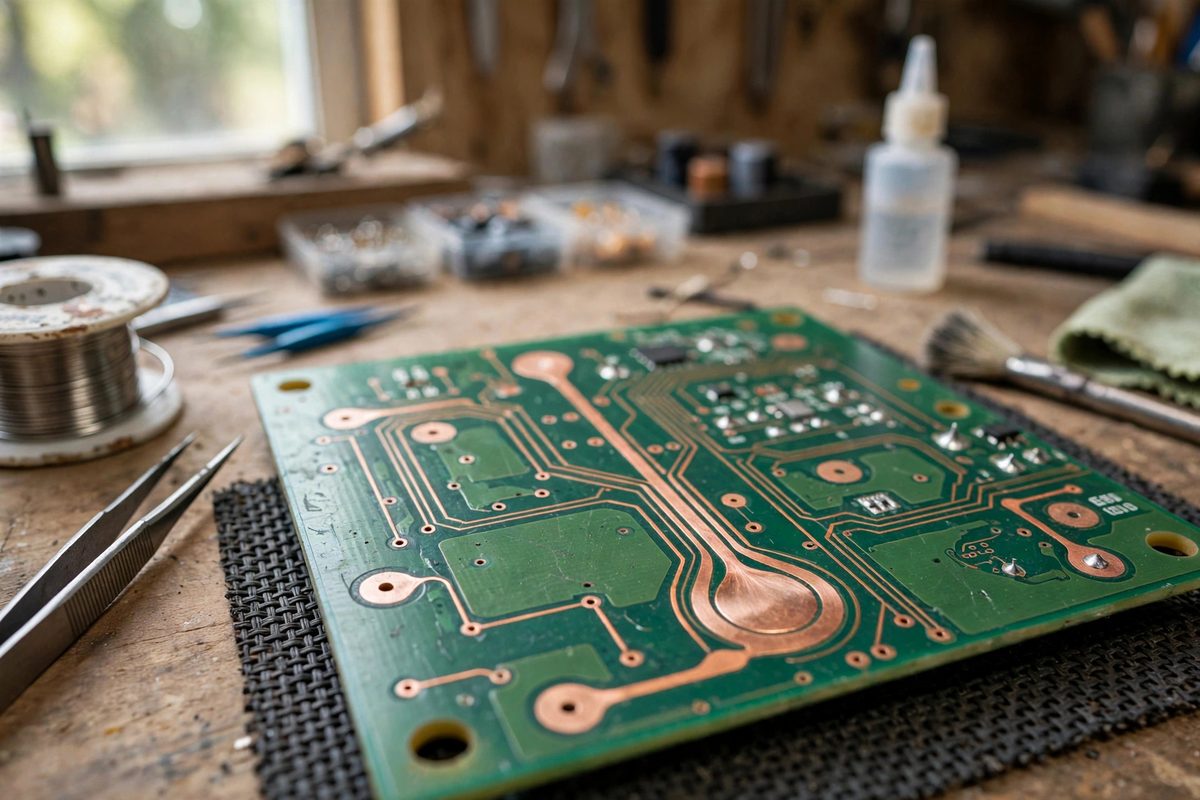
A teardrop is a small fillet of copper where a trace meets a pad, flaring the trace out to meet the pad's edge instead of joining it at a sharp neck. That tiny shape fixes a real manufacturing weakness: the abrupt transition from narrow trace to round pad concentrates mechanical stress and etches unevenly, making the junction the most likely point for a trace to crack or lift. In Eagle layouts, teardrops are added as a finishing step, and they cost nothing but a few minutes while measurably improving board robustness, especially on boards that flex, vibrate, or see thermal cycling.
The Stress Concentration Problem
Where a narrow trace meets a wider pad, the copper cross-section changes abruptly, and abrupt changes concentrate stress. Under board flex, vibration, or thermal expansion cycling, the trace-to-pad junction sees higher local stress than either the trace or the pad alone, and fatigue cracks initiate at the sharp inside corners of the junction. The same geometry causes an etching artifact: during board fabrication, the etchant attacks the narrow neck slightly faster relative to its width, potentially undercutting the junction. A teardrop replaces the abrupt neck with a gradual taper, spreading the mechanical stress over a larger area and giving the etchant a smooth profile to follow. The improvement is disproportionate to the copper involved: a fraction of a millimeter of fillet transforms the junction from the weakest point to an unremarkable one.
Where Teardrops Matter Most
Not every pad needs one. Teardrops pay off where mechanical or thermal stress is real: boards that flex in use, wearable or handheld devices; boards subject to vibration, motor controllers and automotive; boards with large temperature swings, power electronics and outdoor gear; and boards with very narrow traces meeting large pads, where the cross-section change is most extreme. They also help on single-sided or thin boards where the copper adhesion is the limiting factor, since the extra copper area at the junction improves peel resistance. On a rigid, benign, indoor board with generous traces, teardrops are harmless but largely decorative. Apply them where the physics justifies them, and consider them mandatory on any board that will see flexing or wide thermal cycles.
Adding Teardrops in Eagle
Eagle does not teardrop natively in older versions, which is why the technique is associated with ULPs (user language programs) and manual methods. The standard approach is a teardrop ULP that iterates over the board's signals and adds small polygon fillets at each trace-to-pad junction. Run it as one of the last steps before generating Gerbers, after the routing is final, because rerouting after teardropping either destroys the teardrops or leaves orphaned copper. Check the ULP's settings for teardrop size relative to your trace widths: the fillet should flare smoothly without extending so far along the trace that it effectively widens long trace runs or violates clearance to neighbors. After running, inspect the results visually at a few junctions, especially in dense areas, before committing. Newer Eagle and Fusion Electronics versions have improved native support, but the principle is unchanged: teardrops go on last, and they get verified.
Clearance and DRC Considerations
Teardrops add copper, and added copper can violate clearances. The fillet extends the trace's effective width at the junction, which may encroach on neighboring traces, pads, or board edges in dense layouts. Always run the design rule check after teardropping, not before, so the DRC evaluates the actual copper that will be manufactured. If violations appear, the fixes are to reduce the teardrop size in the ULP settings, exclude specific nets or regions from teardropping, or accept that a particular dense area cannot be teardropped and leave it. A useful practice is to teardrop selectively: apply to power and signal traces in open areas, skip the densest BGA fanout regions where clearances are already tight. Selective application captures most of the reliability benefit while avoiding DRC battles.
Teardrops vs. Other Reinforcement
Teardrops are one tool among several for junction reliability. Wider traces at the pad, sometimes called necking up in reverse, achieve similar stress reduction but consume routing space along the whole trace. Filled and capped vias near pads anchor the copper mechanically but add manufacturing cost. Thicker copper, 2oz instead of 1oz, strengthens everything but changes etching behavior and costs more. Teardrops win on cost-effectiveness: they use no extra board area worth mentioning, cost nothing in fabrication, and address the specific failure point directly. They combine well with the other methods where justified, but for most designs they are the first and often the only reinforcement needed at trace-to-pad junctions.
Teardrops are a small finishing step with an outsized reliability payoff on boards that move, vibrate, or cycle thermally. Add them last in Eagle, verify clearances with DRC, and apply them where the stress justifies them. The junctions stop being the weak link, which is exactly the point.
Related Guides
- Trace Creepage and Clearance DRC Setup in Eagle: Creepage and clearance are the two distances that keep high voltage where it belongs on a PCB. Clearance is the shortest distance through air between
- DRC Rules for High-Density Signal Escapes: High-density designs, fine-pitch parts, BGAs, dense connectors, live or die at the escape: the short, brutal routing problem of getting dozens or
- Via Tent Spacing Clearances in Complex Schematics: Via tenting, covering vias with solder mask so the annular ring and hole are sealed, protects against solder bridging, contamination, and accidental
- Net Class Spacing Rules for High Voltage Traces: High voltage on a PCB demands physical distance: traces at different potentials must be spaced far enough apart that the voltage cannot arc across