
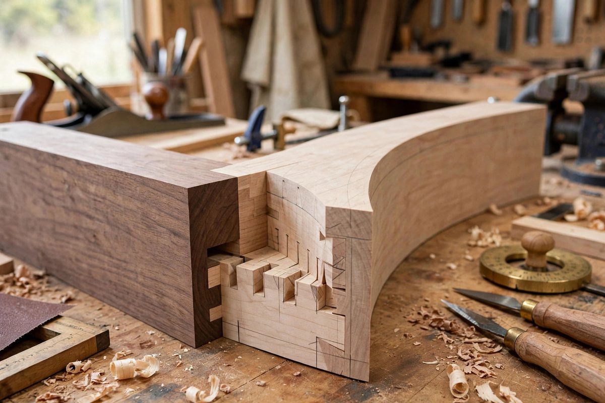
The blind mitered dovetail joins two case sides at a corner so the outside shows only a clean miter while the inside hides interlocking dovetails: the showpiece joint of fine casework. Laying it out on straight edges is demanding enough. On curved carcass edges, where the case side sweeps in an arc, the geometry compounds: the miter angle changes along the curve, the dovetails must follow the arc, and every layout line has to be derived from the actual curve rather than from square. It is advanced joinery, but it decomposes into manageable steps when the curve is treated as the master reference.
Understanding the Joint on a Curve
A blind mitered dovetail has two faces: the miter, a 45-degree (or curve-appropriate) bevel on the outer portion that closes to a seamless corner, and the dovetails behind it, which provide the mechanical lock. On a straight edge, the miter is a constant angle and the dovetails are laid out on a flat plane. On a curved edge, the "miter" is not a single angle but a continuously varying bevel that must match the mating piece's bevel at every point along the arc, and the dovetail sockets must be cut into a curved surface while maintaining their locking geometry. The key realization is that the two mating pieces are complementary sculptures: each one's curves and angles are derived from the other, and the layout must be done with the pieces registered together, not independently from drawings. Layout transferred from a flat drawing introduces errors the joint cannot absorb.
Establishing the Curve as Master
Begin with the curve itself, faired and final, on both mating pieces. The curve is the datum: every subsequent layout line references it. Mark station lines across the curve at regular intervals; these stations are where you will measure and transfer the miter geometry, turning the continuous curve into a series of manageable segments. Make a full-size template of the curve from thin, stable material, and use it to verify both pieces match before any joinery is cut: a mismatch in the base curves makes the joint impossible regardless of layout skill. Number the stations identically on both pieces and on the template; this bookkeeping keeps the two complementary pieces synchronized through the steps ahead.
Laying Out the Miter Along the Arc
At each station, determine the local miter angle: the bevel that, at that point on the curve, will meet the mating piece's bevel to form the closed corner. On a circular arc this can be computed, but on a free curve it is best derived physically: hold the mating pieces in their assembled positions, supported in a dry assembly jig, and scribe the intersection directly. Work station by station, marking the miter line on the edge of each piece. Connect the station marks with a fair line following the curve; this line is the shoulder of the miter. Cut the miter as a series of faceted bevels between stations, then fair the facets into a continuous curved bevel with planes and files. The faceted approach acknowledges that hand tools cut straight; the fairing step blends the facets into the curve. Check the fit dry at every stage; the miter must close along its full length before any dovetail is cut.
Dovetail Layout on the Curved Interior
Behind the miter, the dovetails lock the joint. Lay them out on the interior faces, which are curved, with the tails on one piece and the pins on the other per the usual arrangement. The dovetail angles themselves remain constant, the standard slope, but their positions follow the stations: each tail is centered on its station so the layout stays synchronized with the miter. Cut the tails first, then transfer to the mating piece by direct marking with the pieces registered together, exactly as in straight dovetails, except the registration must hold the curved pieces in their true assembled positions. This is where the dry-assembly jig earns its keep: it holds the curves correctly while you mark. Cut the sockets to the marks, undercutting slightly for a tight fit, and test the joint's draw: it should pull the miter closed as the dovetails seat, which is the mechanical signature of a correct blind mitered dovetail.
Fitting Sequence and Glue-Up
Fit in stages: miter alone first, until it closes perfectly along the curve; then dovetails, fitted one at a time, checking that each seats without forcing the miter open elsewhere. The joint is fitted when it assembles with hand pressure and the miter line is invisible. For glue-up, rehearse the assembly dry with clamps: curved casework needs cauls shaped to the curve to distribute clamping pressure, and the clamping sequence must draw the dovetails home without racking the case. Glue the joint in the same jig used for layout if possible, since the jig already holds the true geometry. Work efficiently: a well-fitted joint needs only moderate clamping pressure, and excessive force distorts the curves you worked hard to fair.
Blind mitered dovetails on curved edges demand that the curve lead and the joinery follow: station the arc, derive the miter physically, synchronize the dovetails to the stations, and fit progressively. It is slow work, and the invisible seam on the finished case is the proof it was worth it.
Related Guides
- Half-Blind Dovetail Depth Setting on Drawer Boxes: Half-blind dovetails are the classic drawer joint for one reason: they are strong, and the mechanical interlock hides the joint from the front of the
- Bridle Joint Tenon Thickness Ratios for Carcass Rails: The bridle joint, an open mortise that receives a full-width tenon, is the workhorse joint for carcass rails and frame corners where the joint will
- Drawbore Mortise and Tenon Pin Shear Stress: Drawboring is the traditional trick of offsetting the peg hole in the tenon slightly toward the shoulder, so driving the peg pulls the joint tight
- Mitering Secret Compartment Keyways in Hardwood Chests: A secret compartment is only as good as its invisibility, and invisibility lives in the details. The keyway, the hidden slot or channel that lets the