
Retro memory boards fail in subtle ways: random glitches, corrupted saves, crashes that come and go with temperature. Often the culprit is not a dead chip but dead bypass capacitors, the small caps that keep each chip's power supply clean. Replacing them is straightforward soldering work, but the details of doing it right on a decades-old board make the difference between a repair and a new problem.
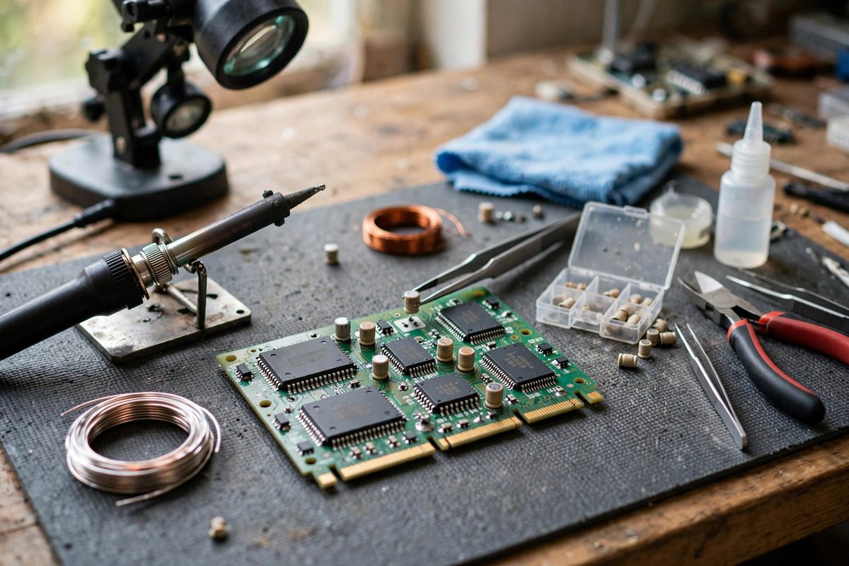
What Bypass Capacitors Do
Every digital chip draws current in sharp pulses as its internal transistors switch. The bypass capacitor sits right at the chip's power pins and supplies those pulses locally, keeping the supply voltage stable. When the capacitor dries out or drifts with age, the pulses instead travel back through the board's power traces, and neighboring chips see the noise as glitches. The symptom is maddeningly intermittent because it depends on which chips switch when. Fresh bypass caps restore the local power reservoirs and the glitches vanish.
Identifying Candidates for Replacement
On retro boards, the bypass caps are the small capacitors clustered near each chip, usually ceramic discs or early tantalums. Tantalums from the era are notorious for failing short, which can drag down the whole power rail; a board that blows fuses or runs hot has a shorted tantalum until proven otherwise. Ceramic discs rarely fail catastrophically but drift in value with age. If the board has a known-good schematic, it tells you the intended values; without one, replace like with like in capacitance and use a voltage rating equal or higher. When in doubt about a specific cap, an ESR meter or capacitance check out of circuit settles it.
Soldering Technique on Old Boards
Old boards have fragile pads and traces. Use a temperature-controlled iron at a moderate setting, and heat the joint just long enough to flow the solder; lingering cooks the adhesive holding the pad to the board. Add a touch of fresh solder to the old joint first, because fresh solder's flux helps the old solder flow and release. Use solder wick or a pump to clear the hole, and never force a lead through a hole that is not fully clear; forcing lifts pads. Support the board so it does not flex while you work, since flexing cracks the very traces you are trying to preserve.
Choosing Replacement Capacitors
Modern multilayer ceramic capacitors outperform the originals in every way that matters: tighter tolerance, lower ESR, longer life. Match the capacitance value and meet or exceed the voltage rating; the physical size should fit the original footprint without stressing the pads. For positions that originally used tantalums, ceramics are a fine and safer substitute. Keep lead lengths short and the cap body close to the board, because the bypass function depends on the cap being electrically close to the chip; long leads add inductance that defeats the purpose.
Testing After Replacement
Before powering up, inspect every joint under magnification: shiny, concave fillets with no bridges to neighboring traces. Check for shorts across the power rails with a meter before applying power, since a solder bridge on a power pin can kill chips instantly. Power up and run the board through its paces, including the operations that used to glitch, and let it run long enough to reach operating temperature. A repair that survives a full warm-up soak is a repair you can trust.
Fresh bypass capacitors are cheap insurance for a retro memory board: identify the tired ones, solder with care for the old pads, keep the replacements close to the chips, and verify before powering. The glitches that haunted the board become a story about the repair.
Related Guides
- Electrolytic Capacitor ESR Testing in Vintage Cartridges: Some vintage game cartridges, particularly those with save batteries, audio circuitry, or special coprocessor chips, contain small electrolytic
- Battery Holder Retrofitting on Memory Save PCBs: Countless retro game cartridges keep their saves alive with a small battery soldered to the PCB, usually a CR2032 or equivalent. After thirty years
- Reflowing Cold Solder Joints on ROM Chip Pins: A vintage game cartridge that boots intermittently, shows garbled graphics, or needs a ritualistic wiggle to work often suffers from cold solder