
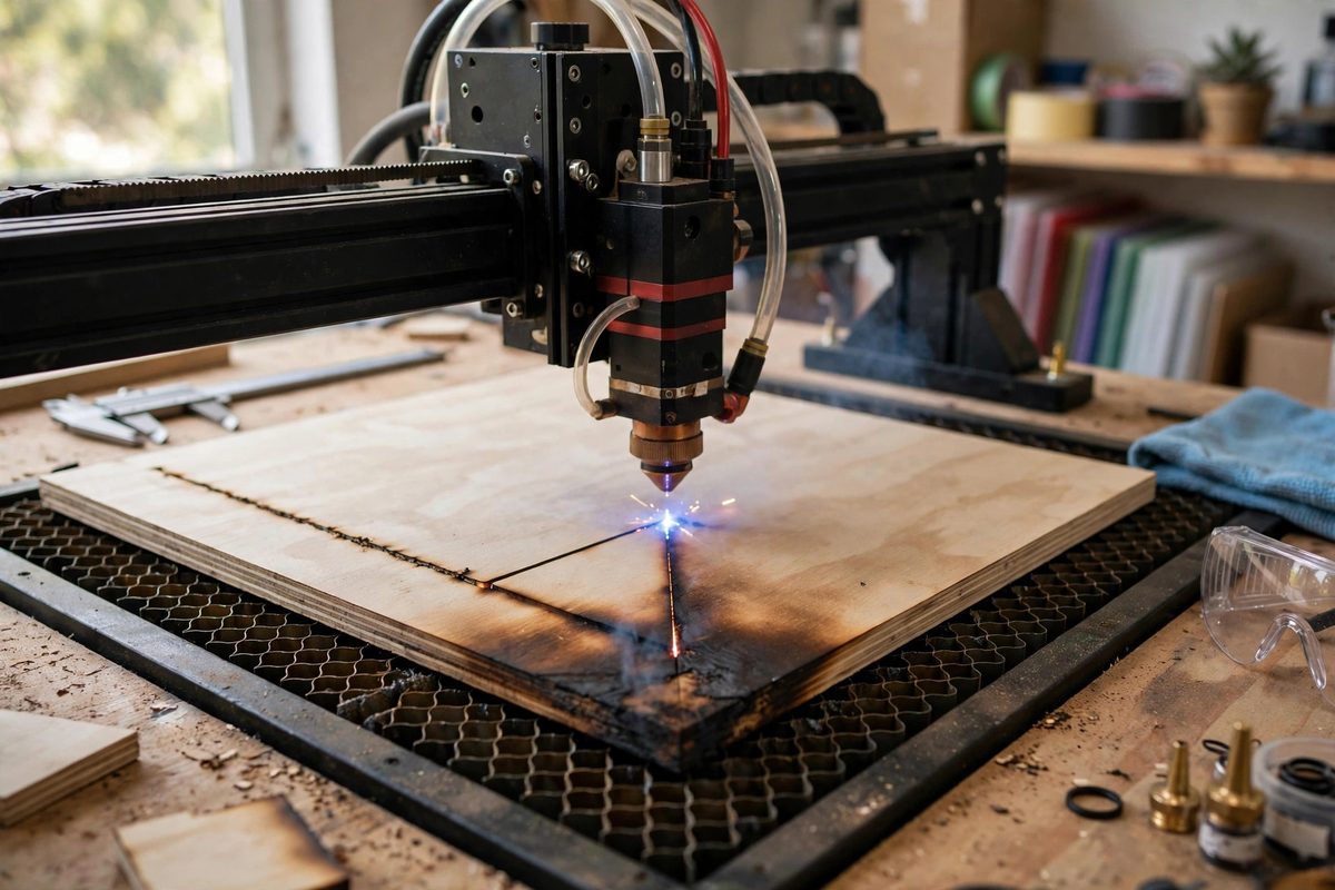
A laser cutting a vector corner has a physics problem: the motion system must slow down to change direction, but the beam keeps delivering full power while it slows, so the corner gets more energy per unit length than the straight sections. The result is the familiar overburned corner, wider kerf, rounded or melted sharp points, sometimes a visible notch. Corner deceleration smoothing manages the power or the motion through the turn so the energy per unit length stays constant and the corner cuts like the straightaway.
Why corners overburn
Energy per unit length is power divided by speed. On a straight cut at constant speed, that ratio is constant and the kerf is uniform. Entering a corner, the motion controller decelerates, the speed drops, the ratio rises, and the material receives extra energy exactly where the geometry is most delicate. The effect is worst on acute angles, where the deceleration is most severe, and on materials with low thermal conductivity, where the extra heat cannot escape into the surrounding stock.
The visible symptoms scale with the severity: slight corner rounding on mild cases, obvious kerf widening and melting on worse ones, and on sharp interior corners, a blown-out notch where the beam sat too long. Any part with tight corners shows this if the controller does nothing about it.
Power ramping through the turn
The most direct fix is to reduce the laser power in proportion to the speed reduction: as the head slows for the corner, the power drops to match, keeping the energy per unit length constant. Many controllers implement this automatically when the feature is enabled, scaling power with the real-time velocity. The setting may be called power ramping, corner power control, or a similar name depending on the controller.
Tuning it means matching the ramp to the machine's actual deceleration profile. Too little ramping and the corners still overburn; too much and the corners undercut, leaving the sharp points uncut or the kerf pinched. Test on the actual material with a pattern of corners at various angles, and adjust until the kerf width is uniform through the turns. The correct setting is material-dependent, since different materials respond differently to the same energy profile.
Motion smoothing and corner rounding in the design
The vector file itself can help. Sharp corners force maximum deceleration; slightly rounded corners, even a tiny radius, let the motion system carry more speed through the turn and reduce the energy spike. When the design tolerates it, replacing mathematically sharp corners with small fillets is the simplest smoothing available, and it is done in the CAD or vector editor before the job ever reaches the laser.
Some controllers also offer motion-level corner smoothing, which rounds the toolpath microscopically at sharp direction changes. This trades a tiny, usually invisible deviation from the programmed path for a much smoother velocity profile. For cutting, where the kerf has finite width anyway, the deviation is almost always acceptable, and the corner quality improvement is significant.
Lead-ins, lead-outs, and pierce points
Corners suffer doubly when the pierce point sits on them: the pierce dumps extra energy starting the cut, and then the corner deceleration adds more. Move pierce points onto straight sections or into waste areas with lead-in moves, so the beam is at full cutting speed and stable power before it reaches any corner. A lead-in also gives the assist gas flow time to establish, which improves the cut quality of everything downstream including the corners.
For interior sharp corners that must stay sharp, consider a slight power reduction just before the corner combined with the lead-in strategy, or an overcut past the corner that is later trimmed. These are refinements for demanding work, but they are the difference between acceptable and excellent on precision parts.
Verifying with the kerf, not the settings
Judge the tuning by measuring the kerf, not by admiring the settings. Cut a test piece with representative corners, measure the kerf width on straights and in corners with calipers or a loupe, and adjust until they match. The numbers do not lie, and they capture the combined effect of power ramping, motion smoothing, and material response in a way that no single setting can.
Constant energy per unit length is the goal; power ramping, design fillets, and pierce placement are the tools. When the kerf measures the same in the corner as on the straight, the profile is right.
Related Guides
- Kerf Compensation in Vector Offset Paths: Every laser cut removes a strip of material, the kerf, and every part comes out smaller than drawn by half the kerf on each side. For decorative work
- Corner Radius Compensation for High Speed Laser Paths: At high cutting speeds, a laser cannot turn a sharp corner without consequence: the motion system must decelerate into the corner and accelerate out
- Lead-In and Lead-Out Geometry in Thin Sheet Cuts: Where the laser pierces thin sheet matters as much as where it cuts. A pierce is violent: the beam dwells and the entry point gets more heat than any
- Node Optimization Rules for Laser Cutting Speeds: A laser cutter's speed is not just the speed setting in the software; it is also the geometry of the vector file. Every node in a path is a point