
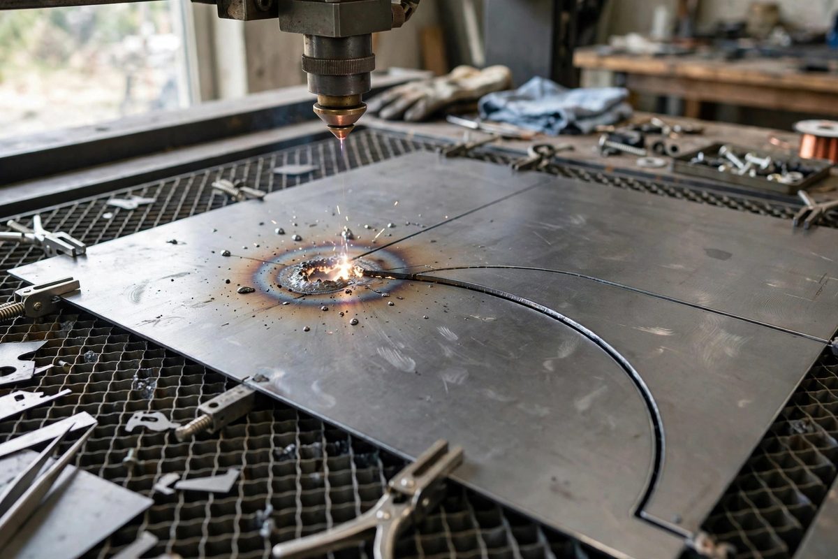
Where the laser pierces thin sheet matters as much as where it cuts. A pierce is violent: the beam dwells and the entry point gets more heat than any other spot on the cut. On thin sheet, that extra heat blows out the entry into an oversized, melted divot, and if the pierce sits on the part's finished edge, the divot is a permanent defect. Lead-ins and lead-outs solve this by starting the cut away from the part edge and sweeping into it, so the ugly pierce happens in scrap and the beam is already moving cleanly when it reaches the profile.
The Pierce Problem on Thin Stock
Piercing requires the beam to burn through the full material thickness from a standstill, which takes a dwell of a fraction of a second to a second or more depending on thickness and power. During that dwell, heat spreads sideways from the pierce point, melting a zone wider than the kerf. On thick plate this is a minor cosmetic issue; on thin sheet, where the kerf is narrow and the part edge is delicate, the pierce crater can be several times the kerf width, with a raised rim of resolidified metal. Starting the cut directly on the profile line puts that crater on the finished edge. It also risks incomplete penetration at the very start of motion: the beam begins moving before the pierce is fully through, dragging a tail of partial cut. Both defects vanish when the pierce is relocated into waste material.
Lead-In Shapes and Their Uses
A lead-in is the entry path from the pierce point to the profile. The simplest is a straight line: pierce at a standoff distance, travel straight to the profile, begin the contour. It works but enters the profile at whatever angle the line meets it, which can leave a small witness mark. An arc lead-in is better for most work: the path curves into the profile tangentially, so the beam is already traveling along the profile's direction when it arrives, and the transition is seamless. The arc radius should suit the material thickness and the part geometry: larger arcs give gentler entries but need more scrap clearance around the part. For delicate profiles or tight inside corners, a short straight lead-in perpendicular to the edge minimizes the approach distance where space is limited. The lead-in must exceed the pierce-affected zone so the beam cuts cleanly before reaching the part: a few millimeters usually suffices on thin sheet.
Lead-Outs: Finishing Cleanly
The end of the cut has its own problem. When the beam finishes the profile and stops, or when it cuts the part free and the piece shifts, the endpoint can suffer the same dwell overheating as the pierce, plus the mechanical issue of the cut part moving as it releases. A lead-out continues the beam past the profile end into scrap, so the stop and any dwell happen off the part. On closed profiles, the lead-out often overlaps the lead-in slightly, ensuring the contour is fully severed: without overlap, the start point may retain a tiny uncut tab that keeps the part attached. That tab tears on removal, leaving a worse defect than a clean lead-out would have. For parts cut in sequence from one sheet, plan lead-outs so the beam ends positioned sensibly for the next pierce, minimizing travel without dragging across finished parts.
Placement Strategy Across a Sheet
Lead-ins consume scrap space around each part, which affects nesting efficiency. The strategy is to place pierces and leads in the waste regions between parts, sharing scrap zones where possible. On thin sheet, parts are often nested tightly, so lead-in length becomes a nesting constraint: a part that needs a long arc lead-in needs clearance around it, which pushes neighbors apart. Balance the lead length against material utilization; a slightly shorter lead-in that still clears the pierce zone wastes less sheet. Also consider cut order: cutting interior features before exterior profiles prevents the part from shifting mid-cut, and placing lead-ins on interior cutouts where the waste is the cutout itself costs no extra material. Common-line cutting is usually avoided on thin sheet, where pierce damage would affect both parts sharing the edge.
Thin-Sheet Specifics
Thin sheet amplifies every lead-in consideration because the parts are light and flimsy. A part cut free can lift or flutter in the assist gas stream, so the lead-out and cut order should release small parts last or leave micro-tabs holding them until the sheet is unloaded. Heat distortion is the other thin-sheet enemy: even with good leads, excessive heat input warps the sheet, so keep power and speed balanced and avoid clustering pierces in one area, which concentrates heat. The pierce itself can often use reduced power or a pulsed pierce on thin stock, shrinking the crater and allowing shorter lead-ins. Test the full sequence, pierce, lead-in, profile, lead-out, on a scrap corner of the actual sheet before running the nest: thin sheet varies, and the settings that worked on the last batch may need a nudge.
Lead-ins and lead-outs are the difference between laser cutting and laser butchery on thin sheet. Pierce in the scrap, sweep into the profile tangentially, overlap at the close, and cut the part free last. The edges will look like the drawing, not like the pierce.
Related Guides
- Kerf Compensation in Vector Offset Paths: Every laser cut removes a strip of material, the kerf, and every part comes out smaller than drawn by half the kerf on each side. For decorative work
- Node Optimization Rules for Laser Cutting Speeds: A laser cutter's speed is not just the speed setting in the software; it is also the geometry of the vector file. Every node in a path is a point
- Corner Radius Compensation for High Speed Laser Paths: At high cutting speeds, a laser cannot turn a sharp corner without consequence: the motion system must decelerate into the corner and accelerate out
- Corner Deceleration Smoothing in Vector Kerf Profiles: A laser cutting a vector corner has a physics problem: the motion system must slow down to change direction, but the beam keeps delivering full power