
At high cutting speeds, a laser cannot turn a sharp corner without consequence: the motion system must decelerate into the corner and accelerate out, dwelling the beam and over-burning the corner. Corner radius compensation, rounding the toolpath's corners in the design or the controller, keeps the speed up and the corners clean. It is a small design habit with a large effect on cut quality at production speeds.
Why Sharp Corners Over-Burn
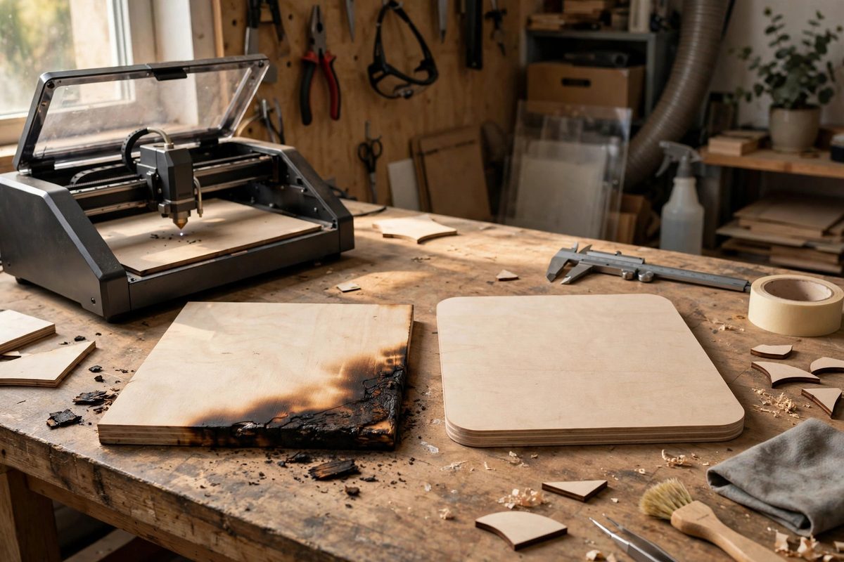
A laser cutting head has mass, and changing direction requires decelerating to near zero velocity at a sharp corner. While the head slows, the beam keeps delivering full power to a nearly stationary spot, dumping excess heat into the corner. The result is the familiar rounded, widened, or discolored corner on parts cut too fast: the design said sharp, the physics said melt. The effect worsens with speed, power, and material thickness; thin material at moderate speed may tolerate sharp corners, while thick material at high speed will not. Controllers with corner power ramping reduce the power through the deceleration, which helps, but the fundamental issue is the dwell. The geometric fix is to eliminate the need to stop: replace the sharp corner with a radius the head can traverse at speed.
How Corner Radii Fix It
A radiused corner lets the motion system blend through the direction change without stopping; the head follows the arc at a maintained speed, and the beam's heat input stays uniform. The required radius depends on the speed and the machine's acceleration capability: faster cutting and lower acceleration need larger radii. As a practical approach, add small radii, even a fraction of a millimeter, to outside corners in the vector design; inside corners get the beam's kerf radius naturally but still benefit from designed rounding on the toolpath. The radius does not need to be large to work; it needs to be large enough that the controller's lookahead can plan a continuous-speed path through it. Test on the actual machine, since controller behavior varies.
Designing Compensation Into the File
Add corner radii in the vector design stage, not as an afterthought. In CAD or vector software, fillet the sharp outside corners of the cut paths with a radius suited to the material and speed; keep a standard radius for common jobs so the compensation is consistent. For parts where a truly sharp outside corner is functionally required, consider whether the corner can be achieved with a secondary operation, or accept the slower speed that corner demands; physics does not negotiate. Inside corners of cutouts cannot be sharper than the beam's kerf radius anyway, so design them with at least that radius and add a little more for speed. Document the standard corner radius in the shop's cutting notes so every designer applies it.
Controller Features That Help
Modern laser controllers offer features that complement geometric compensation. Corner power control reduces laser power proportional to the head's actual velocity through the corner, which directly counters the over-burn; enable it and tune it for the material. Lookahead algorithms plan the speed profile across multiple path segments, smoothing through radiused corners far better than through sharp ones; the radii give the lookahead something to work with. Some controllers also offer automatic corner rounding, which applies a small radius to sharp corners in the toolpath itself; this is convenient but less controlled than designing the radii deliberately. Use the controller features together with designed radii, not instead of them; the combination produces corners that are both fast and clean.
Verifying Corner Quality
Inspect test cuts under magnification: a well-compensated corner shows uniform kerf width and consistent edge color through the turn, while an over-burned corner shows a widened kerf, discoloration, or a blob of re-solidified material. Measure critical corner dimensions, since over-burn also changes the part's geometry; a corner that melts wider than drawn is out of tolerance. Run the verification at the intended production speed, because a corner that looks fine at test speed may fail at full speed. Once the radius and controller settings are proven for a material and thickness, lock them into the shop standard; corner quality then becomes automatic rather than a per-job experiment.
High-speed laser corners need radii, not sharp points: design small fillets into outside corners, enable corner power control, and verify at production speed. The head keeps moving, the heat stays even, and the corners come out as drawn.
Related Guides
- Kerf Compensation in Vector Offset Paths: Every laser cut removes a strip of material, the kerf, and every part comes out smaller than drawn by half the kerf on each side. For decorative work
- Node Optimization Rules for Laser Cutting Speeds: A laser cutter's speed is not just the speed setting in the software; it is also the geometry of the vector file. Every node in a path is a point
- Corner Deceleration Smoothing in Vector Kerf Profiles: A laser cutting a vector corner has a physics problem: the motion system must slow down to change direction, but the beam keeps delivering full power
- Lead-In and Lead-Out Geometry in Thin Sheet Cuts: Where the laser pierces thin sheet matters as much as where it cuts. A pierce is violent: the beam dwells and the entry point gets more heat than any