
Cycloidal drives deliver enormous gear reduction in a compact package with near-zero backlash, which makes them attractive for robot joints that need high torque in a small space. But the magic depends on tolerances: the cycloidal disc's lobe profile, the ring pins it rolls against, and the eccentric bearing that drives it must all fit within tight windows, or the drive binds, wears rapidly, or develops the backlash it was chosen to avoid. Understanding which tolerances matter, and why, is the key to building or buying a cycloidal joint that survives.
How the drive works, briefly
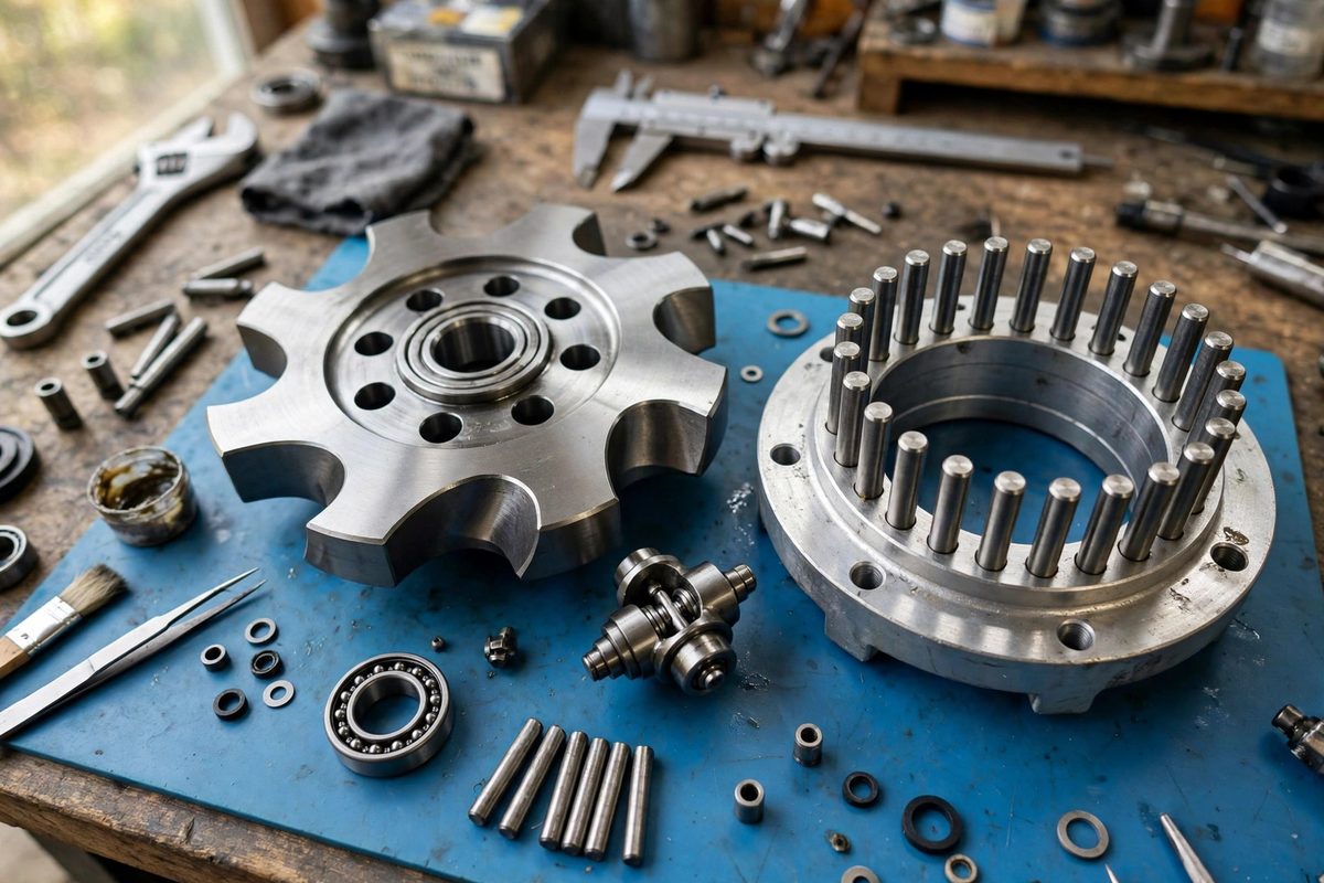
A cycloidal drive has three main elements: an input shaft with an eccentric lobe, a cycloidal disc with a wavy outer profile riding on that eccentric, and a ring of fixed pins surrounding the disc. As the input turns, the eccentric wobbles the disc, and the disc's lobes engage the ring pins one after another, advancing the disc by a tiny rotation per input revolution. Output pins through oversized holes in the disc collect that slow rotation while absorbing the wobble.
The reduction ratio comes from the difference between the lobe count and the pin count, often a single lobe difference producing ratios of 30:1 or more in one stage. Nearly half the lobes share the load at any moment, which is why the torque capacity is so high for the size. Every one of those load-sharing contacts depends on the geometry being right.
The critical tolerance: disc profile to pin circle
The most sensitive dimension is the relationship between the cycloidal disc's lobe profile and the ring pin positions. The disc must roll against the pins with contact maintained but without interference: too tight and the drive binds or requires excessive input torque; too loose and contact is lost, load sharing collapses, and backlash appears. The working clearance at each pin contact is typically measured in hundredths of a millimeter, and it must be consistent around the full circle.
This tolerance stack includes the disc profile accuracy, the pin diameter consistency, the pin circle position accuracy, and the eccentricity of the input bearing. Each contributes, and the sum must stay within the clearance window. For a maker-built drive, this means the disc profile should be machined or ground rather than 3D printed if real torque is expected; printed discs can demonstrate the kinematics but rarely hold the tolerances for loaded service.
Eccentric bearing and output pin clearances
The eccentric bearing sets the disc's wobble amplitude, which must match the profile geometry: wrong eccentricity and the lobes either jam against the pins or float free. The bearing itself needs to be a quality unit with minimal play, since any slop in the eccentric shows up directly as lost motion at the output.
The output pins pass through holes in the disc that are deliberately oversized to accommodate the wobble. The oversize amount is a calculated value, not a guess: too little and the pins bind as the disc wobbles; too much and the output develops backlash. The pin-to-hole clearance is one of the drive's designed-in tolerances, and it interacts with the disc profile clearance, so both must be right together.
Materials and wear
High-torque cycloidal joints need hardened, wear-resistant contact surfaces: hardened steel pins, a hardened or hard-coated disc, and proper lubrication. The contact stresses at the pin-lobe interfaces are high precisely because so much torque flows through small contact zones. Soft materials deform, the profile changes, clearances grow, and the drive degrades from precision reducer to sloppy gearbox.
Lubrication matters more than in many gearboxes because the contact is rolling with some sliding, and the many simultaneous contacts generate heat under load. A proper grease, retained in the housing, extends the tolerance life enormously. A dry-running cycloidal drive wears its precision away quickly.
Buying versus building
Commercial cycloidal reducers exist because the tolerances are genuinely demanding to achieve in a home shop. For a joint that must deliver real torque reliably, a purchased reducer is often the economical choice once machining time and scrap rate are counted honestly. Building one makes sense for learning, for unusual sizes, or for low-torque applications where the tolerances can relax. Know which situation you are in before committing to either path.
Whichever route, verify the finished drive: check for smooth rotation through the full range with no tight spots, measure backlash at the output under light load reversal, and run it under gradually increasing load while listening for distress. A good cycloidal joint runs quietly and smoothly; binding, clicking, or roughness means a tolerance is wrong, and running it that way only makes it worse.
The profile, the pins, the eccentricity, and the materials: hold those four and the cycloidal drive delivers the torque density and precision that make it worth the trouble.
Related Guides
- Harmonic Drive Backlash Measurement in Robot Arms: Harmonic drives, also called strain wave gears, are the precision gearboxes inside most robot arms: enormous reduction ratios, near-zero backlash
- Magnetic Absolute Encoder Drift in Robot Arm Joints: A robot arm that cannot trust its own joint angles is not a robot arm. It is a suggestion. Magnetic absolute encoders are popular in hobby and
- Brushless Field-Oriented Control Setup: Field-oriented control, or FOC, is the technique that makes brushless motors run smoothly, quietly, and efficiently at any speed, by controlling the
- Planetary Gearhead Efficiency Limits Under Load: Planetary gearheads, the compact concentric reducers that multiply a motor's torque, are rated with efficiency numbers that look reassuring on the