
Harmonic drives, also called strain wave gears, are the precision gearboxes inside most robot arms: enormous reduction ratios, near-zero backlash when new, and compact enough to live inside a joint. "Near-zero" is doing heavy lifting in that sentence, because harmonic drives do have measurable lost motion, and it grows with wear. Measuring backlash in a harmonic-drive joint tells you whether the arm's positioning errors come from the gearbox or from somewhere else, and tracking it over time tells you when a drive is wearing out. The measurement is straightforward; interpreting it requires understanding what a harmonic drive actually is.
How Harmonic Drives Differ From Conventional Gears
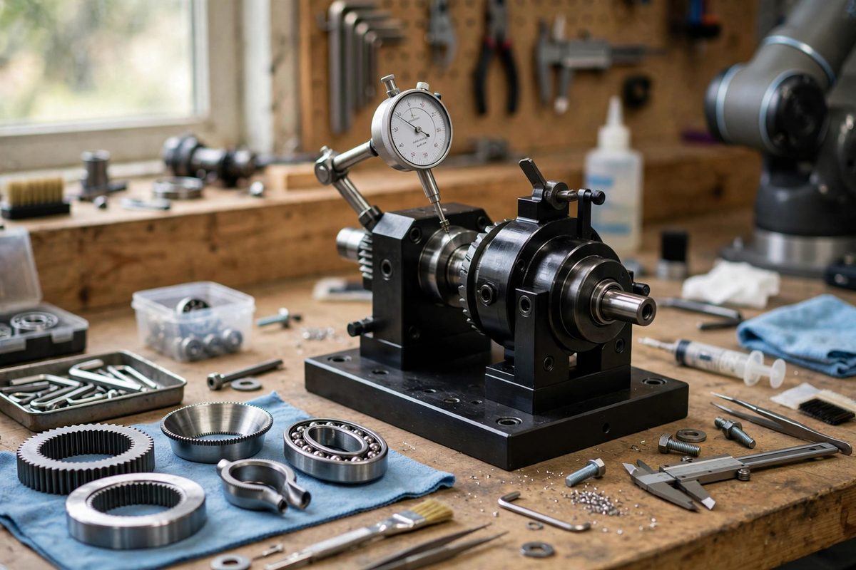
A harmonic drive has three parts: a circular spline (a rigid ring with internal teeth), a flexspline (a flexible cup with external teeth, slightly fewer than the ring), and a wave generator (an elliptical plug that deforms the flexspline into engagement with the ring at two opposite points). As the wave generator rotates, the engagement points travel around, and the tooth-count difference advances the flexspline slowly: a large reduction from a tiny mechanism. There are no conventional gear teeth sliding past each other with clearance; the teeth are always engaged at the two contact zones. This is why backlash is near zero when new: there is no tooth-to-tooth gap to take up. But "lost motion" still exists from the flexspline's elastic deformation under load, the wave generator bearing's play, and the cumulative effect of tooth wear. What you measure as backlash in a harmonic joint is mostly elastic windup plus wear, not gear clearance.
The Measurement Setup
Measuring joint backlash means measuring the output's lost motion for a reversing input. Fix the joint's input side, or command the motor to hold position, then apply a known reversing torque to the output link and measure the angular displacement with a dial indicator or an encoder on the output. The standard procedure: load the output in one direction, zero the indicator, reverse the load, and read the displacement. That displacement, converted to angle at the joint, is the lost motion. The load magnitude matters: too light and you measure only the free play without seating the elastic components; too heavy and you measure elastic deflection of the whole arm structure rather than the joint. Use a load representative of the arm's working loads, applied smoothly without impact. Repeat several times and average; harmonic lost motion has a small hysteresis component that varies slightly cycle to cycle.
Separating Gearbox From Structure
The measurement above captures everything between the motor and the indicator: the harmonic drive, the joint bearings, the link structure, and the mounting. To attribute the lost motion correctly, measure at multiple points. An encoder on the motor shaft versus an encoder on the output isolates the gearbox plus output bearing from the motor and its coupling. A dial indicator on the link near the joint versus at the link's end separates joint lost motion from link bending: bending grows with distance from the joint, joint lost motion does not. This decomposition matters because the fixes differ completely. Worn harmonic drive means gearbox service or replacement; loose joint bearings mean bearing adjustment; link bending means the arm is being asked to do work beyond its stiffness. Chasing gearbox backlash when the real problem is a flexing link wastes a good gearbox.
What the Numbers Mean
Interpretation needs a baseline: measure the joint when new or newly serviced and record the lost motion under the standard test load. That baseline, typically arc-minutes for a healthy harmonic joint, is the reference for all future measurements. A gradual increase over months or years of service is normal wear: the flexspline teeth and the wave generator bearing wear, and the elastic behavior changes. The concern threshold is application-dependent: a pick-and-place arm tolerates far more lost motion than a machining or precision assembly arm. Set the threshold from the arm's positioning requirements, not from the gearbox datasheet alone: the question is whether the total lost motion still fits inside the task's error budget. Sudden increases, or lost motion accompanied by new noise, roughness, or torque ripple, indicate damage rather than wear and deserve immediate investigation.
Tracking Wear Over Time
Single measurements diagnose; trends predict. Log the lost motion per joint at regular service intervals, under the same test load and procedure, and plot it. A steady linear trend lets you forecast when the joint will cross the application's threshold, which turns gearbox replacement from an emergency into scheduled maintenance. An accelerating trend warns of progressive damage, like a failing wave generator bearing, that may cascade into destroying the flexspline if run to failure. Keep the test procedure identical between measurements: same load, same temperature range, same measurement point, because lost motion in harmonic drives is temperature-sensitive (the flexspline's elasticity changes with temperature) and procedure-sensitive. Consistency in measurement is what makes the trend trustworthy.
Harmonic drive backlash is really lost motion: elastic windup plus wear in a gearbox with no conventional tooth clearance. Measure it with reversing loads, separate it from structural flex, baseline it when healthy, and track the trend. The numbers tell you whether the arm is aging gracefully or asking for service.
Related Guides
- Cycloidal Drive Tolerances for High-Torque Joints: Cycloidal drives deliver enormous gear reduction in a compact package with near-zero backlash, which makes them attractive for robot joints that need
- Magnetic Absolute Encoder Drift in Robot Arm Joints: A robot arm that cannot trust its own joint angles is not a robot arm. It is a suggestion. Magnetic absolute encoders are popular in hobby and
- Brushless Field-Oriented Control Setup: Field-oriented control, or FOC, is the technique that makes brushless motors run smoothly, quietly, and efficiently at any speed, by controlling the
- Planetary Gearhead Efficiency Limits Under Load: Planetary gearheads, the compact concentric reducers that multiply a motor's torque, are rated with efficiency numbers that look reassuring on the