
A robot arm that cannot trust its own joint angles is not a robot arm. It is a suggestion. Magnetic absolute encoders are popular in hobby and mid-range arms because they report a true shaft angle on power-up with no homing move, they tolerate dust and grease that would kill an optical disk, and they cost a fraction of a precision optical unit. But builders regularly discover that the reported angle wanders: the joint reads a degree off after a long move, or the zero point seems to migrate between sessions. That wander has causes, and most of them are mechanical and magnetic rather than electronic. Understanding where drift comes from lets you design it out instead of fighting it in software.
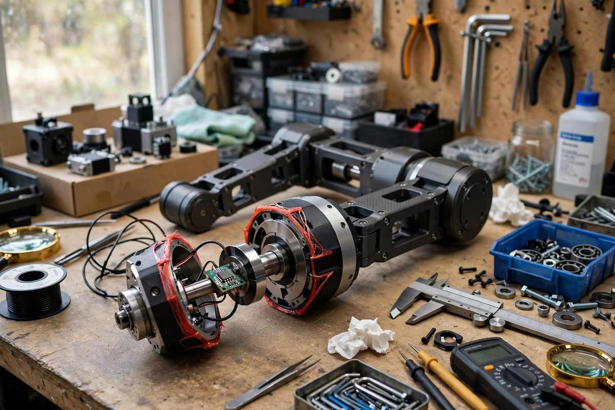
How the sensor actually measures angle
A magnetic absolute encoder reads the field of a small diametrically magnetized disk mounted on the shaft, using an array of Hall elements on the sensor chip. The chip computes the field angle from the relative strengths across the array and converts it to a digital position. Two things about this matter for drift. First, the measurement depends on the geometry of the field at the chip, so anything that moves the magnet relative to the sensor, even slightly, changes the reading. Second, the chip assumes a clean, symmetric dipole field. Anything that distorts that field, from a nearby steel screw to a magnetized shaft, introduces a systematic error that looks exactly like drift. The electronics are usually innocent. The magnet and its neighborhood are where the trouble lives.
Mechanical sources: air gap and eccentricity
The air gap between the magnet face and the sensor chip is the most sensitive dimension in the whole assembly. These sensors are specified for a gap of roughly a millimeter or two, and moving outside that window degrades accuracy fast: too close and the field saturates the Hall elements, too far and the signal sinks into noise. Worse than a wrong gap is a varying gap. Shaft end play, a magnet glued slightly off-center, or a sensor board that flexes under cable tension all modulate the gap as the joint rotates, producing a periodic error that repeats once per revolution. That once-per-rev signature is the fingerprint of eccentricity. Fix it mechanically: seat the magnet concentrically with a proper fixture rather than by eye, control end play with shims or a preload, and mount the sensor board on standoffs instead of letting it float on its wires.
Magnetic interference from the neighborhood
The sensor cannot tell the magnet's field from any other field, so the magnetic environment around the joint is part of the design. Steel fasteners near the sensor distort the dipole and add offset errors. Worse, the motor itself is a giant electromagnet sitting centimeters away, and its stray field varies with current, which means the encoder error can vary with motor load. That load-dependent flavor of drift is maddening to debug because the arm is accurate when still and wrong when working. Keep ferrous hardware away from the sensor, or replace the nearest fasteners with non-magnetic stainless or brass. Route motor phase wires away from the sensor, and if the geometry forces them close, twist the phase conductors so their fields partially cancel. Some builders add a thin magnetic shield, but shielding near a position sensor is a delicate business: a poorly placed shield distorts the very field you are trying to read.
Temperature drift and what to do about it
Both the magnet and the Hall elements change with temperature. Common magnet materials lose a fraction of their field strength as they warm, and the sensor's own offset drifts with die temperature. In practice this shows up as a slow migration of the zero point as the arm warms up under load, often on the order of fractions of a degree over tens of degrees of temperature change. For a pick-and-place arm that is usually irrelevant. For an arm doing precision assembly or long machining-style toolpaths, it matters. The practical mitigations are straightforward: let the arm warm up before precision work, keep the sensor away from the motor's heat path, and if your controller supports it, apply a temperature compensation table measured once on your actual hardware. Do not try to compensate with a generic coefficient from a datasheet. Measure your joint, on your arm, across your operating range.
Calibration that actually holds
Many builders calibrate the encoder once against a known reference and then wonder why the calibration decays. Calibration can only correct errors that are stable, so the first step is always to make the mechanics and magnetics stable using the fixes above. Once they are, a lookup table built by stepping the joint through its range against an independent reference, such as a precision protractor or a second temporary encoder, can remove the repeatable portion of the error, including the harmonic content from slight eccentricity. Store the table per joint, since every magnet seating is unique. Re-check the calibration after any disassembly, any magnet handling, and any change to nearby hardware, because all of those alter the field geometry the table was built on. A calibration is a photograph of a specific physical arrangement. Change the arrangement and the photograph is stale.
When drift is really a mounting problem in disguise
A useful diagnostic rule: if the error repeats with shaft angle, suspect geometry, meaning eccentricity, tilt, or a varying air gap. If the error varies with motor current, suspect magnetic interference from the drive. If it creeps slowly over minutes, suspect temperature. If it jumps between power cycles, suspect that the magnet shifted in its seat or that a nearby ferrous part was magnetized by a fault current. Work through those signatures before touching the firmware, because no amount of filtering fixes a magnet that is physically wandering. The filter just hides the evidence until the error exceeds what the controller can absorb.
Magnetic encoders are excellent joint sensors when their physical installation is treated as part of the measurement. Control the air gap, seat the magnet concentrically, keep steel and motor fields at a distance, account for temperature, and calibrate against the real assembly. Do that and the drift most builders fight simply never appears.
Related Guides
- Harmonic Drive Backlash Measurement in Robot Arms: Harmonic drives, also called strain wave gears, are the precision gearboxes inside most robot arms: enormous reduction ratios, near-zero backlash
- Cycloidal Drive Tolerances for High-Torque Joints: Cycloidal drives deliver enormous gear reduction in a compact package with near-zero backlash, which makes them attractive for robot joints that need
- Brushless Field-Oriented Control Setup: Field-oriented control, or FOC, is the technique that makes brushless motors run smoothly, quietly, and efficiently at any speed, by controlling the
- Planetary Gearhead Efficiency Limits Under Load: Planetary gearheads, the compact concentric reducers that multiply a motor's torque, are rated with efficiency numbers that look reassuring on the