
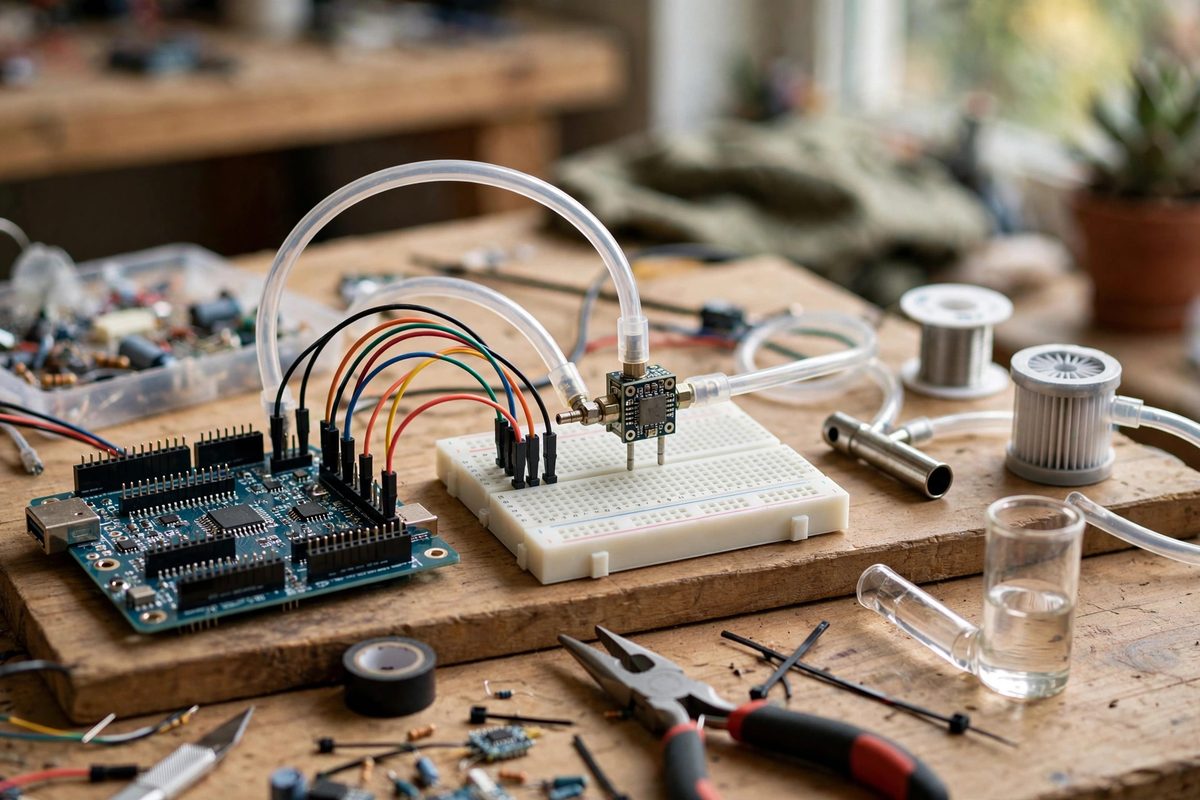
Differential pressure sensors measure the difference between two pressure ports, the quantity that matters for airflow, filter monitoring, liquid level, and pitot tubes. Many modern sensors communicate over SPI, delivering digital readings straight to the microcontroller. But a raw reading is not a measurement: the sensor's output must be calibrated, converted from counts to pressure units with the sensor's transfer function, corrected for offset and temperature, and validated against reality. Calibration is what turns a chip that reports numbers into an instrument that reports pressure.
The Sensor's Transfer Function
Most SPI differential pressure sensors output a digital value that maps linearly to pressure across the sensor's rated range. The datasheet gives the transfer function: typically, the output at zero differential pressure (the offset) and the output at full scale, from which any reading converts by linear interpolation. Some sensors include the calibration coefficients in onboard memory, readable over SPI; others expect you to hard-code the datasheet values.
Read the datasheet's transfer function section carefully, because the details vary: some sensors output signed values centered at mid-scale, others output unsigned values with a defined zero offset, and the pressure range may be symmetric (±) or one-sided. Applying the wrong transfer function produces readings that are confidently, precisely wrong.
Zero Offset Calibration
Every differential sensor has a zero offset: the reading it reports when both ports see the same pressure. The datasheet specifies a typical offset and a tolerance, and individual sensors vary within that tolerance. For accurate low-pressure measurements, calibrate the offset in your actual installation: with both ports open to the same still air, take a series of readings, average them, and store the result as the zero reference subtracted from all subsequent measurements.
Repeat the zero calibration whenever the installation changes and periodically during long deployments. Offset drifts with temperature, aging, and mechanical stress; a sensor zeroed on the bench in spring may read differently mounted in a hot enclosure in summer. Auto-zero routines, which re-capture the offset during known no-flow conditions, are standard practice in permanent installations.
SPI Communication Details
Getting clean readings starts with correct SPI: the right mode (clock polarity and phase per the datasheet), an appropriate clock speed (slower is more reliable over long wires), and proper chip-select timing. Read the sensor's status bits along with the data; many sensors flag data-ready, diagnostic faults, or out-of-range conditions in the same transaction, and ignoring the status means missing the sensor telling you not to trust the reading.
- Keep SPI traces short and away from noisy signals; corrupted bits masquerade as pressure spikes.
- Match the SPI mode exactly; a mode mismatch produces plausible-looking garbage.
- Respect the sensor's conversion timing; reading faster than the sensor updates returns stale data.
- Average multiple readings in firmware; the sensor's noise floor drops with the square root of the sample count.
Temperature Compensation
Pressure sensors drift with temperature, and differential measurements at low pressures are especially vulnerable because the signal is small relative to the drift. Many SPI sensors include an onboard temperature sensor and factory temperature compensation; verify that the compensation is actually enabled and applied, since some sensors require the host to perform the compensation math using coefficients from the datasheet.
For critical measurements, characterize the installed sensor across the expected temperature range: log readings at known zero differential while varying the temperature, and build a correction table or fit a curve. This is real calibration work, and it is what separates a hobby reading from an instrument reading.
Validating Against a Reference
The final calibration step is comparison against a trusted reference: a manometer, a calibrated pressure source, or a second known-good sensor. Apply known differential pressures across the range of interest and record the sensor's reported values; the comparison reveals gain errors, nonlinearity, and hysteresis that the datasheet's typical specifications do not promise about your specific unit.
Document the calibration: the zero offset, the transfer function used, the temperature corrections, and the date. A sensor with documented calibration is an instrument; a sensor without it is a suggestion. When the measurements matter, the paperwork matters too.
Apply the transfer function, zero in place, mind the SPI details, compensate temperature, and validate against a reference. The sensor gives you counts; calibration gives you pressure, and the difference is the entire job.
Related Guides
- Differential Signal Filtering on Long SPI Sensor Buses: SPI was designed for short hops between chips on the same board, and it shows when you stretch it across a room. The fast edges, single-ended
- SPI Bus Signal Ringing and Termination on Arduino: SPI is the fast lane for Arduino sensor communication, but speed brings signal integrity problems that slow protocols never show. Ringing, the
- Mitigating I2C Bus Capacitance on Sensors: I2C works beautifully on a breadboard and then falls apart when you run it across a room. The culprit is almost always bus capacitance: every
- Mitigating I2C Bus Capacitance on Sensors: I2C works beautifully on a breadboard and then falls apart when you run it across a room. The culprit is almost always bus capacitance: every
- Schmitt Trigger Noise Filtering on Hall Effect Pins: Hall effect sensors detect magnets without contact, perfect for counting rotations, sensing positions, and building tachometers. But the raw output