
SPI is the fast lane for Arduino sensor communication, but speed brings signal integrity problems that slow protocols never show. Ringing, the oscillation that appears on clock and data lines after each transition, is the most common: the square wave overshoots, undershoots, and rings like a struck bell before settling. At low speeds the ringing settles before the receiver samples, so nobody notices. Push the clock faster, lengthen the wires, or add a second device, and the ringing is still going when the sample happens, corrupting bits. Termination, done correctly, kills the ringing at its source.
What Causes Ringing
Every wire is a transmission line: it has inductance along its length and capacitance to ground, and a fast edge launched into it reflects off impedance mismatches. The Arduino's output pin has low impedance, roughly tens of ohms; a length of hookup wire has higher characteristic impedance, roughly around a hundred ohms; the receiving sensor pin has very high impedance, essentially an open circuit. When the fast edge hits the high-impedance receiver, it reflects back toward the driver, bounces off the low-impedance driver, and returns, each round trip smaller than the last. That decaying bounce is the ringing you see on a scope. The longer the wire, the longer each round trip takes, and the more round trips fit inside one clock period. Short wires on a breadboard at modest speeds hide the problem; longer cables or fast clocks expose it.
Why SPI Suffers More Than I2C
SPI's architecture concentrates the problem. It uses a dedicated clock line driven hard by the master, with edges as fast as the Arduino can produce, and it has no built-in acknowledgment or error checking at the hardware level: a corrupted bit is simply wrong data, silently. I2C, by contrast, uses open-drain lines with pull-up resistors, which inherently slow the edges and damp reflections, and its protocol includes acknowledgment bits that catch some errors. SPI also commonly runs much faster, which shrinks the timing margins. The practical consequence: an SPI sensor that works perfectly on a breadboard with short jumpers can start returning garbage when moved to a project box with longer wiring, and the failure looks like a software bug, intermittent wrong readings, when it is actually a signal integrity problem.
Series Termination: The Simple Fix
The standard fix for a point-to-point SPI bus driven by one master is series termination: a small resistor in series with each driven line, placed close to the driver (the Arduino end). The resistor raises the driver's effective source impedance to roughly match the wire's characteristic impedance, so the launched edge is absorbed instead of reflecting. Typical values run from a few tens of ohms up to around a hundred ohms; the exact value is not critical because the goal is approximate matching, not precision. Start with something in the middle of that range on the clock line, which is the most critical, and add resistors to MOSI and the chip-select lines if problems persist. MISO, driven by the sensor back toward the Arduino, can benefit from a resistor at the sensor end on long runs. The tradeoff is edge speed: the resistor and the wire capacitance form a low-pass filter, so excessive resistance rounds the edges and can itself cause timing failures. Use the smallest value that kills the ringing.
Layout Practices That Prevent Ringing
Termination fixes reflections, but good layout reduces them at the source. Keep SPI wires short: every extra inch is extra round-trip time for reflections. Route clock and data lines close together, ideally as a loose bundle or twisted group, which keeps their electrical environment consistent. Keep a ground wire or ground return alongside the signals; a signal without a nearby return path has higher effective inductance and rings worse. Avoid sharp routing through breadboard jungles of long jumpers when speed matters; a short, direct connection beats a tidy-looking but long one. If the design needs distance, consider buffering: a proper line driver at the Arduino end and the termination at the far end handles cable runs that passive resistors alone cannot. And keep the SPI clock as slow as the application allows: the easiest signal integrity fix is needing less of it.
Diagnosing With a Scope
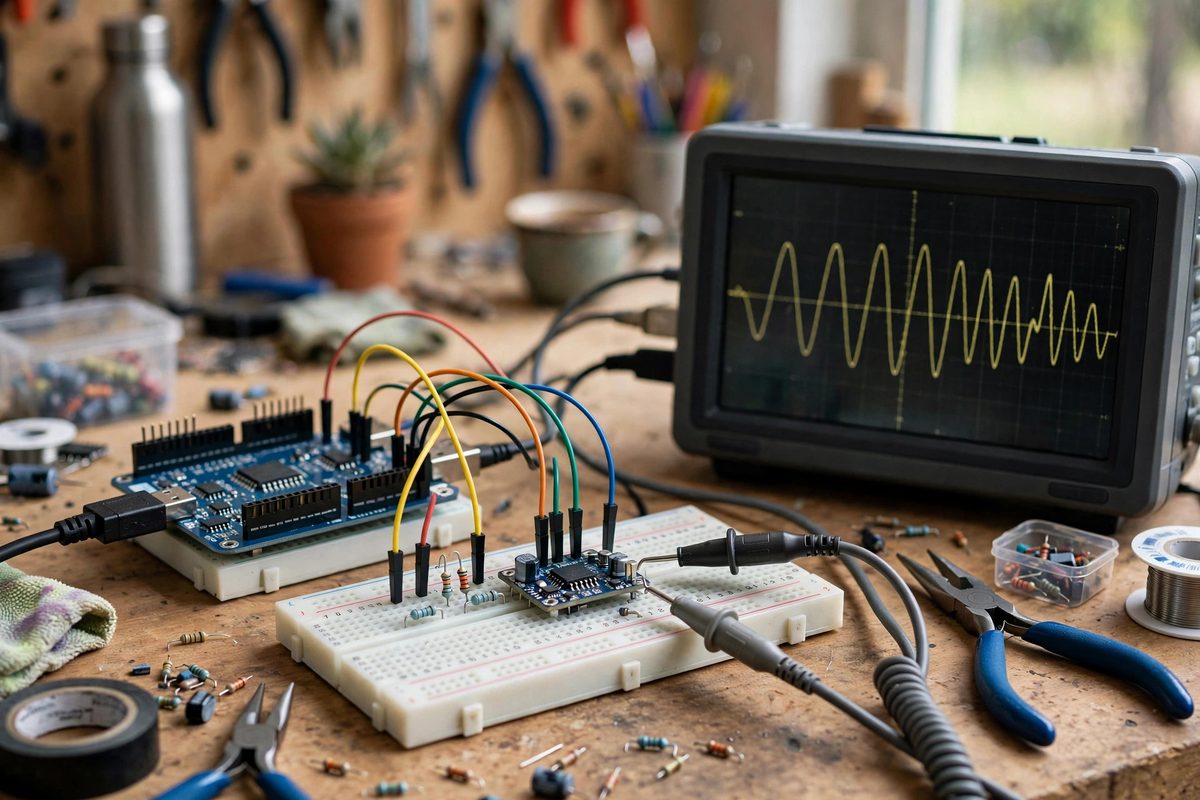
Ringing is invisible without an oscilloscope, which is why it gets misdiagnosed as software trouble. If you have access to a scope, probe the clock line at the sensor end, not the Arduino end: the receiver sees the worst of the reflections. A clean signal shows a sharp edge settling quickly; a ringing signal shows overshoot past the supply rails and multiple oscillations. Add the series resistor and watch the ringing collapse in real time; adjust the value until the edge is clean without becoming visibly rounded. No scope? Diagnose empirically: if errors appear as speed or wire length increases and vanish when you slow the clock or shorten the wires, you are looking at signal integrity, and series termination is the first thing to try. Also try the fix of last resort for stubborn cases: slowing the SPI clock in software costs nothing and often restores reliability immediately.
SPI ringing is a physics problem with a one-resistor solution. Match the source to the wire with series termination at the driver, keep runs short with a proper ground return, and verify at the receiver end. The sensor data will stop lying to you.
Related Guides
- Differential Signal Filtering on Long SPI Sensor Buses: SPI was designed for short hops between chips on the same board, and it shows when you stretch it across a room. The fast edges, single-ended
- Differential Pressure Sensor Calibrations on SPI: Differential pressure sensors measure the difference between two pressure ports, the quantity that matters for airflow, filter monitoring, liquid
- Mitigating I2C Bus Capacitance on Sensors: I2C works beautifully on a breadboard and then falls apart when you run it across a room. The culprit is almost always bus capacitance: every
- Mitigating I2C Bus Capacitance on Sensors: I2C works beautifully on a breadboard and then falls apart when you run it across a room. The culprit is almost always bus capacitance: every
- Schmitt Trigger Noise Filtering on Hall Effect Pins: Hall effect sensors detect magnets without contact, perfect for counting rotations, sensing positions, and building tachometers. But the raw output