
Hall effect sensors detect magnets without contact, perfect for counting rotations, sensing positions, and building tachometers. But the raw output of a Hall sensor near its switching threshold is noisy: the signal chatters between high and low as the magnetic field hovers at the trip point. A Schmitt trigger cleans that chatter into a single decisive transition. Understanding the pairing makes Hall sensing reliable.
Why Hall Outputs Chatter
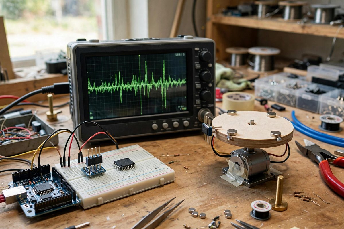
A Hall sensor switches its output when the magnetic field crosses a threshold. Near that threshold, electrical noise, mechanical vibration, and tiny variations in the magnet's position make the field wobble above and below the trip point rapidly. The sensor faithfully reports each crossing, producing a burst of fast transitions instead of one clean edge. An Arduino counting pulses then counts dozens of phantom events per real one; a position sensor reports flickering states. This is not a defective sensor; it is the correct behavior of a threshold detector in a noisy world. The fix is hysteresis: making the turn-on threshold different from the turn-off threshold, so small wobbles cannot cause repeated switching.
How the Schmitt Trigger Provides Hysteresis
A Schmitt trigger is a comparator with positive feedback, which creates two thresholds: a higher one for rising signals and a lower one for falling signals. The output switches high when the input crosses the upper threshold, and does not switch back low until the input falls below the lower threshold. The gap between the thresholds is the hysteresis band, and any noise smaller than that band cannot cause chatter. Many Hall effect sensor chips include a Schmitt trigger on the output already; these are the digital Hall switches, as opposed to linear Hall sensors that output an analog voltage. When using a linear Hall sensor, or when the built-in hysteresis is insufficient, an external Schmitt trigger, a dedicated chip or a comparator wired with feedback, provides the same cleanup.
Choosing Hysteresis for the Application
The hysteresis band should exceed the peak noise but remain smaller than the real signal swing. Too little hysteresis and the chatter persists; too much and the sensor becomes insensitive, missing real events or adding phase delay to the detection. For a tachometer counting a spinning magnet, generous hysteresis is fine, since the signal swing is large and the goal is one count per revolution. For precise position sensing near the trip point, the hysteresis must be small enough not to shift the effective switching position unacceptably. Check the Hall sensor's datasheet for its built-in operate and release points; the difference is the built-in hysteresis. If the application needs more, add it externally; if it needs less, choose a different sensor, since built-in hysteresis cannot be reduced.
Wiring and Layout for Clean Signals
Even with a Schmitt trigger, good wiring practice matters. Keep the sensor's power supply clean: add a decoupling capacitor at the sensor, since supply noise modulates the switching thresholds. Route the sensor's output away from noisy lines like motor leads; capacitive coupling from a PWM motor driver into a Hall signal line defeats the trigger's cleanup. Use a pull-up resistor of appropriate value on open-drain Hall outputs; too weak a pull-up makes the rising edge slow and noise-sensitive before the Schmitt trigger even sees it. Twist or shield long sensor cables in electrically noisy environments. The Schmitt trigger handles threshold noise, but it cannot fix a signal buried in interference; give it a decent signal to work with.
Software Debouncing as a Complement
Hardware hysteresis and software debouncing solve different parts of the problem. The Schmitt trigger eliminates the rapid threshold chatter, producing clean edges; software debouncing then handles the slower mechanical realities, like a magnet that genuinely passes the sensor twice due to vibration. A simple approach is to timestamp each detected edge in the Arduino and ignore edges that arrive impossibly soon after the previous one, based on the application's maximum real event rate. Use interrupts for the clean Schmitt-triggered signal rather than polling, since polling can miss short pulses. Together, hardware hysteresis for the electrical noise and software discipline for the mechanical behavior produce Hall sensing that simply works, count after count.
Hall sensors chatter at their thresholds; Schmitt triggers silence them with hysteresis: use sensors with built-in hysteresis where possible, add external triggering when needed, wire cleanly, and complement with software debouncing. One clean edge per event, every time.
Related Guides
- Differential Signal Filtering on Long SPI Sensor Buses: SPI was designed for short hops between chips on the same board, and it shows when you stretch it across a room. The fast edges, single-ended
- Mitigating I2C Bus Capacitance on Sensors: I2C works beautifully on a breadboard and then falls apart when you run it across a room. The culprit is almost always bus capacitance: every
- Mitigating I2C Bus Capacitance on Sensors: I2C works beautifully on a breadboard and then falls apart when you run it across a room. The culprit is almost always bus capacitance: every
- SPI Bus Signal Ringing and Termination on Arduino: SPI is the fast lane for Arduino sensor communication, but speed brings signal integrity problems that slow protocols never show. Ringing, the
- Differential Pressure Sensor Calibrations on SPI: Differential pressure sensors measure the difference between two pressure ports, the quantity that matters for airflow, filter monitoring, liquid