
SPI was designed for short hops between chips on the same board, and it shows when you stretch it across a room. The fast edges, single-ended signaling, and lack of error checking that make SPI simple also make it fragile over distance: long wires act as antennas and transmission lines, picking up noise and distorting the clock and data signals until the sensor readings come back corrupted. Differential signaling fixes this by sending each signal as a complementary pair, and filtering cleans up what remains.
Why long SPI fails
Three problems grow with wire length. First, noise pickup: long single-ended wires couple capacitively and inductively to every noise source nearby, from motors to mains wiring, and SPI's fast edges give noise plenty of bandwidth to corrupt. Second, signal integrity: the wire's capacitance rounds off the fast SPI edges, and reflections from impedance mismatches ring on the transitions, so the receiver sees a smeared clock instead of a crisp one. Third, ground bounce: the sensor and the Arduino no longer share a clean common ground over distance, and the difference appears directly on the single-ended signals.
The symptoms are intermittent: readings that are mostly right with occasional garbage, sensors that work on the bench and fail in the installation, failures that come and go with nearby equipment switching. That intermittency is the signature of a signal integrity problem rather than a code problem.
Differential signaling: the core fix
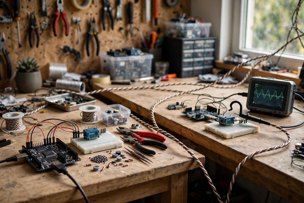
Differential signaling sends each SPI line as two complementary signals on a twisted pair: when one goes high, the other goes low. The receiver reads the difference between them, which means any noise picked up equally by both wires cancels out. This common-mode rejection is why differential buses like RS-485 run reliably over hundreds of meters while single-ended SPI struggles past one.
The practical approach is a differential transceiver at each end of the bus: one chip converts the Arduino's single-ended SPI signals to differential pairs for the cable run, and a matching chip at the sensor end converts back. Twisted-pair cable, with each SPI signal on its own pair, maximizes the noise cancellation. This adds hardware, but it converts a fundamentally unreliable long bus into a fundamentally reliable one.
Filtering what the differential pair cannot fix
Differential signaling rejects common-mode noise but does not fix everything. Series resistors at the driver end of each line slow the signal edges slightly, reducing the high-frequency energy that causes ringing and crosstalk; values in the tens of ohms are typical, tuned by observing the signals. RC filters on the receiver end roll off noise above the SPI clock rate, though they must be designed carefully so they do not round the edges past what the receiver can read.
Ferrite beads on the cable suppress high-frequency common-mode noise that the twisted pair does not fully cancel, particularly useful when the cable runs near motors or switching power supplies. Place them at the receiver end where the noise does its damage.
Clock speed: the free variable
The simplest reliability improvement costs nothing: slow the SPI clock. Signal integrity problems scale with edge rate and frequency, and many sensors work fine at a fraction of their maximum clock speed. If the application does not need maximum throughput, dropping the clock by a factor of two or four often turns a marginal bus into a solid one. This is the first thing to try before adding hardware, and it combines well with the hardware fixes for long runs.
Grounding and shielding practice
Give the differential bus a clean ground reference: a dedicated ground conductor in the cable, connected at both ends, keeps the common-mode voltage within the transceivers' range. Shielded twisted-pair cable with the shield grounded at one end (to avoid ground loops) adds another layer of protection in electrically noisy environments. Keep the SPI cable routed away from power cables and motor wiring; physical separation is the cheapest filter there is.
Slow the clock first, then go differential with twisted pairs, then filter the residuals. Long SPI buses are entirely workable once the signaling matches the distance.
Related Guides
- Differential Pressure Sensor Calibrations on SPI: Differential pressure sensors measure the difference between two pressure ports, the quantity that matters for airflow, filter monitoring, liquid
- SPI Bus Signal Ringing and Termination on Arduino: SPI is the fast lane for Arduino sensor communication, but speed brings signal integrity problems that slow protocols never show. Ringing, the
- Schmitt Trigger Noise Filtering on Hall Effect Pins: Hall effect sensors detect magnets without contact, perfect for counting rotations, sensing positions, and building tachometers. But the raw output
- Mitigating I2C Bus Capacitance on Sensors: I2C works beautifully on a breadboard and then falls apart when you run it across a room. The culprit is almost always bus capacitance: every
- Mitigating I2C Bus Capacitance on Sensors: I2C works beautifully on a breadboard and then falls apart when you run it across a room. The culprit is almost always bus capacitance: every