
A shop tool crib, the storage system that holds the shop's shared tooling, needs to be built right the first time; rebuilding storage is pure overhead. Orthographic projection drawings, the flat front, top, and side views of traditional drafting, communicate the crib's design precisely enough to build from, and learning to draft them is a skill that pays off on every future project.
Why orthographic for shop furniture
Orthographic views show true dimensions: in the front view, heights and widths are exact; in the top view, widths and depths are exact. There is no perspective distortion to misread, which means a builder can take measurements directly from the drawing. For a tool crib, where compartments must fit specific tools and the whole unit must fit a specific wall, that dimensional honesty matters. A perspective sketch is nice for visualization; orthographic views are for building.
The three essential views
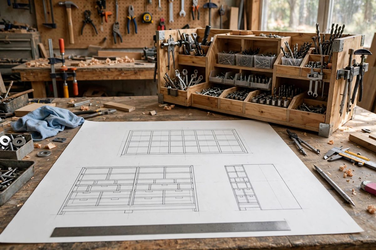
Draft the front view first: the crib as seen straight on, showing overall height and width, compartment divisions, and door or drawer layouts. Then the top view: the footprint, depth, and how compartments arrange front to back. Then a side view: the depth profile, shelf spacing, and any sloped or stepped features. Keep the views aligned with each other, front above top in the standard arrangement, so dimensions can be projected between views. Add a section view wherever the interior construction needs explaining, such as a drawer slide detail or a compartment divider joint.
Dimensioning discipline
Dimension every feature needed to build the crib, and dimension it once, in the view where it reads most clearly. Use a consistent dimension style: extension lines, arrowheads, and numerals placed to be read from the bottom and right. Chain-dimension the compartment widths across the front view so they add up to the overall width; the arithmetic check catches errors. Note the material thickness wherever it affects the fit, because a compartment designed for a tool plus clearance fails if the divider thickness was forgotten.
Planning for the tools
A tool crib is designed around its contents. List the tools it must hold, with their actual dimensions, before drafting; the compartments are sized to the tools, not to round numbers. Allow clearance for hands as well as tools: a compartment exactly the tool's size is unusable. Group tools by use, keep heavy tools low, and plan for growth; a crib packed to capacity on day one is obsolete on day two. The drawing should show the tool layout, not just empty boxes, so the design can be evaluated against reality.
Joinery and construction notes
The drawings should specify how the crib goes together: the joinery for the carcass, the shelf supports, the door hinges, the back panel attachment. A detail view of a typical joint, drawn larger, covers all the identical joints without redrawing each one. Note the fasteners and their spacing; a crib full of heavy tools needs its joinery specified, not improvised. The notes on the drawing are part of the design, not an afterthought.
From drawing to build
Build from the drawings, not from memory, and update the drawings when reality intervenes. If a compartment needs resizing during the build, mark the change on the drawing so the record matches the crib. The finished drawings become the shop's documentation: when the crib needs modification or a matching unit gets built, the drawings are the starting point. Good documentation compounds; every future project starts from a better place.
Draft the three views true, dimension everything once and clearly, design around the actual tools, specify the joinery, and keep the drawings honest through the build. The tool crib will fit its wall, hold its tools, and stand as proof that the drawing was worth the time.
Related Guides
- Isometric Dimensioning Rules for Shop Blueprints: An isometric drawing shows a part in three dimensions on a single sheet, which makes it the fastest way to communicate a design to someone who has to
- Vector Callout Standards for Exploded Assembly Guides: An exploded assembly guide shows how parts fit together by drawing them separated along their assembly axes, and callouts are what connect each
- Callout Typography Hierarchy in Workshop Technical PDF: Technical PDFs for the workshop, assembly guides, machine manuals, project plans, live or die by their callouts: the labels, notes, and annotations
- Exploded Isometric Assembly Rules for Hardware Kits: An exploded view is the clearest way to show a maker how a hardware kit goes together: every part floats along its assembly axis, spaced so nothing