
An isometric drawing shows a part in three dimensions on a single sheet, which makes it the fastest way to communicate a design to someone who has to build it. But dimensions placed carelessly on an isometric view confuse more than they clarify: extension lines collide with the drawing, numbers sit at unreadable angles, and the builder guesses. A few firm rules keep isometric dimensions clean and unambiguous.
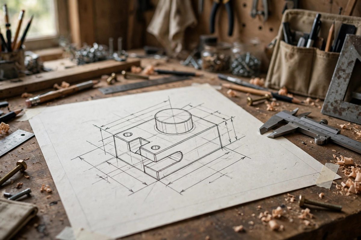
Align dimensions to the isometric planes
In isometric projection, every edge of the object runs parallel to one of three axes, and dimensions must live in the planes those axes define. A dimension measuring along one axis sits in the plane containing that axis, with its extension lines parallel to a second axis. This means dimension text tilts to match the plane: it is never horizontal unless the dimension lies in a horizontal plane. Readers of shop drawings expect this; text aligned to the isometric planes reads naturally, while horizontal text floating over a tilted view looks wrong and gets misread.
Place dimensions outside the view
Keep dimensions outside the object's outline whenever possible. Extension lines should start with a small gap from the object's edge, never touching it, and extend just past the dimension line. When several dimensions stack along one axis, stagger them outward from the object with the longest dimension outermost, so extension lines do not cross dimension lines. Crossing lines are the primary source of misreading: at a glance, a crossed extension line looks like a dimension line, and the builder measures the wrong feature.
One dimension per feature, in the clearest view
Dimension each feature once, in the plane where its true length shows. An edge that runs along an isometric axis shows its true length and dimensions cleanly; a diagonal across a face does not, and dimensioning it invites error. For holes and circular features, which appear as ellipses in isometric, give the diameter with a leader pointing to the ellipse rather than trying to dimension across it. Overall dimensions, the bounding box of the part, go outermost and give the builder the first sanity check: if the part does not match the overalls, something is wrong before any detail matters.
Text and arrow discipline
Keep all numerals the same size and oriented to read from the bottom or right of the sheet, following the plane alignment rule. Arrowheads should be filled, consistent in size, and touch the extension lines precisely; sloppy arrowheads make precise numbers look approximate. Avoid dimensioning to hidden edges in isometric views: if a feature cannot be seen, its dimension belongs on an orthographic view, not forced onto the pictorial. A shop blueprint set pairs the isometric overview with orthographic details for exactly this reason.
What not to dimension
Leave off dimensions the builder does not need: cosmetic fillets, non-critical clearances, and features fully defined by other dimensions. Every unnecessary dimension is a chance for contradiction; when two dimensions disagree, the builder must stop and ask, and the drawing has failed. Check the dimension set for redundancy before issuing: each feature located once, each size given once, overall sizes confirming the parts add up.
Plane-aligned, outside the view, once per feature, clean text. Isometric dimensions done this way let the builder work from the drawing without a single question, which is the whole point.
Related Guides
- Exploded Isometric Assembly Rules for Hardware Kits: An exploded view is the clearest way to show a maker how a hardware kit goes together: every part floats along its assembly axis, spaced so nothing
- Drafting Orthographic Projections for Shop Tool Cribs: A shop tool crib, the storage system that holds the shop's shared tooling, needs to be built right the first time; rebuilding storage is pure
- Vector Callout Standards for Exploded Assembly Guides: An exploded assembly guide shows how parts fit together by drawing them separated along their assembly axes, and callouts are what connect each
- Callout Typography Hierarchy in Workshop Technical PDF: Technical PDFs for the workshop, assembly guides, machine manuals, project plans, live or die by their callouts: the labels, notes, and annotations