
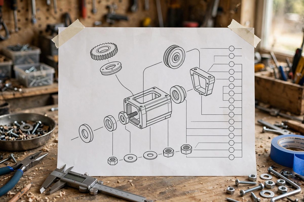
An exploded assembly guide shows how parts fit together by drawing them separated along their assembly axes, and callouts are what connect each floating part to its name, number, and place in the parts list. Done well, callouts make a complex assembly readable at a glance. Done poorly, they turn the drawing into a thicket of crossing lines and mystery numbers. Standards exist for callouts precisely because assembly guides are used under pressure: at the bench, on the factory floor, in the field. Consistency is not fussiness; it is usability.
Balloons, numbers, and the parts list
The standard callout is the balloon: a circle containing the part's item number, connected by a leader line to the part itself. Item numbers run in a logical sequence, usually following the assembly order or grouping by subassembly, and every number in the drawing must appear exactly once in the accompanying parts list with its description and quantity. Never number a part in the drawing that is missing from the list, and never list a part that has no balloon; either error sends the assembler hunting for something that is not there. Keep balloon text large enough to read at the guide's intended viewing distance, and keep all balloons the same size so no part looks more important than another. When an assembly has subassemblies, consider a numbering scheme that shows the grouping, such as 2.1 and 2.2 for parts of subassembly 2, so the structure of the product is visible in the numbers themselves.
Leader lines that do not lie
A leader line must point unambiguously at the part it identifies. The standard practice is a thin line ending in a dot or short arrow at the part, angled to avoid crossing other leaders wherever possible. The dot endpoint is traditional for pointing at a surface; the arrow is used when pointing at an edge or a specific feature. Keep leaders short and route them outward to the balloons, which live in the clear space around the drawing, never buried inside the part cluster. Leaders should not cross each other, should not cross dimension lines, and should meet their balloons at a consistent angle, usually horizontal. When two identical parts appear in different places, one balloon with leaders to both is acceptable, and the parts list quantity covers the count. Every crossing or ambiguous leader is a small lie the reader has to resolve, and they add up.
Exploded layout discipline
The explosion itself follows rules. Parts separate along their true assembly axes: a bolt pulls straight out along its thread axis, a cover lifts off perpendicular to its mating face. Keeping the explosion honest to the assembly direction teaches the reader how the thing goes together, not just what the parts look like. Maintain consistent spacing between exploded parts so the eye can follow each axis, and keep the overall arrangement compact enough that leaders stay short. Centerlines drawn through the explosion axes help enormously, especially for stacked assemblies like fasteners through plates. Resist the urge to explode every tiny part to the same distance; group small hardware near its parent part so the relationships stay visible. The drawing should read as an assembly paused mid-explosion, not as parts scattered by wind.
Line weights, text, and color restraint
In vector guides, line weight carries meaning. Part outlines get the heaviest weight, hidden and secondary lines get lighter weights, and leaders and balloons get the lightest, so the callout system visually recedes behind the parts it serves. All text, including balloon numbers and the parts list, should use the same clean typeface in consistent sizes; mixing fonts in a technical guide reads as sloppiness. Use color sparingly and functionally: a single accent color for balloons can help them stand out, but the guide must remain fully usable in grayscale, since it will be photocopied and printed in black and white. Never rely on color alone to distinguish parts or callouts.
Checking the guide before release
Proof an assembly guide the way an assembler will use it: hand it to someone unfamiliar with the product and watch them assemble from it. Every hesitation marks a callout failure. Verify that balloon numbers match the parts list, that quantities are correct, that every part in the list appears in the drawing, and that the explosion order matches the real assembly sequence. Check the guide at its actual printed size, because leaders and balloon text that look fine zoomed in on screen often crowd together on paper. A guide that survives this testing earns the trust it asks for.
Callout standards feel rigid until you have debugged an assembly from a guide that ignored them. Then the rigidity reads as what it is: respect for the reader's time and attention.
Related Guides
- Exploded Isometric Assembly Rules for Hardware Kits: An exploded view is the clearest way to show a maker how a hardware kit goes together: every part floats along its assembly axis, spaced so nothing
- Callout Typography Hierarchy in Workshop Technical PDF: Technical PDFs for the workshop, assembly guides, machine manuals, project plans, live or die by their callouts: the labels, notes, and annotations
- Isometric Dimensioning Rules for Shop Blueprints: An isometric drawing shows a part in three dimensions on a single sheet, which makes it the fastest way to communicate a design to someone who has to
- Drafting Orthographic Projections for Shop Tool Cribs: A shop tool crib, the storage system that holds the shop's shared tooling, needs to be built right the first time; rebuilding storage is pure