
An animatronic eye that can look around needs two axes of rotation, pan and tilt, and a blink mechanism on top of that. The geometry of how those axes are arranged determines whether the eye moves smoothly and naturally or binds, wobbles, and looks mechanical. Getting the gimbal geometry right is the difference between a creature that feels alive and one that feels like a desk toy.
Pan-Tilt Order and the Gimbal Center
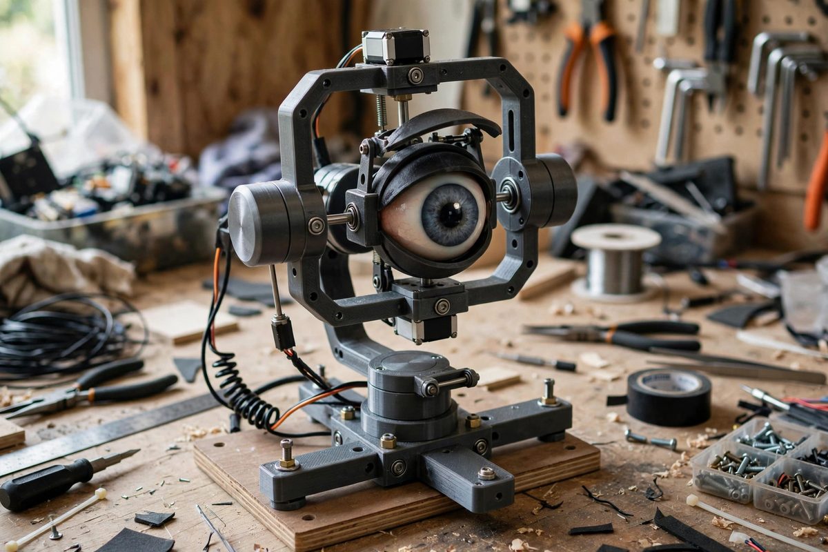
A dual-axis gimbal is usually built as nested yokes: an outer yoke provides pan (side to side), and an inner yoke carried by the outer provides tilt (up and down), or the reverse. The critical design rule is that both axes of rotation must intersect at the center of the eyeball. If the tilt axis passes in front of or behind the ball center, tilting the eye also translates it, and the eye appears to lurch forward or sink back in its socket as it looks up and down. Viewers read that translation instantly as wrong, even if they cannot name it. Design the yokes so the two pivot axes cross exactly at the sphere center, and verify with the actual ball installed before you finalize any bracket.
Which Axis Goes Outside
Putting pan on the outside and tilt on the inside is the common arrangement, and it suits most character heads. The outer pan yoke can be anchored to the skull frame on both sides, giving a stiff mount, while the inner tilt yoke only carries the eyeball itself. This order also keeps the tilt servo or linkage compact, since it rides on the pan stage and moves with it. The alternative, tilt outside and pan inside, can work when the head is very narrow, but it puts the heavier assembly on the moving stage and tends to wobble. Whichever order you choose, the outer stage must be rigid: any flex in the outer yoke shows up as slop in the inner axis, and slop in an eye reads as a dead, unfocused stare.
Blink Mechanism Geometry
Blinking is usually a separate single-axis motion, an eyelid rotating about a horizontal axis above the eye, or two lids meeting from top and bottom. The lid pivot axis should sit slightly above and behind the eyeball center so the lid sweeps along the ball surface with even clearance. If the pivot is too far forward, the lid edge digs into the ball at the bottom of the stroke; too far back and the lid never fully closes. Drive the lid with a linkage or a small servo with enough speed for a convincing blink, which is much faster than most builders expect: a natural blink completes in roughly a tenth to two tenths of a second. Slow blinks look sleepy or broken. Program or rig the blink as a quick close with a slightly slower open, because that asymmetry is what real eyelids do.
Linkage Design and Range of Motion
Eyes need roughly 30 to 40 degrees of travel in each direction for a natural look; more than that starts to look cartoonish unless the character calls for it. Design the linkages so the servo operates in the middle of its travel at eye-center, which keeps the motion symmetric and avoids the nonlinear ends of servo travel where resolution is coarse. Use ball joints or flexible pushrods at both ends of each link so the mechanism does not bind as the geometry changes through the range. A common failure is a pushrod that works fine at center but jams at full tilt because the builder never checked the extremes. Cycle every axis through its full range by hand, feeling for tight spots, before you ever power it up.
Keeping It Quiet and Reliable
An eye mechanism lives inches from the audience in many puppet and animatronic applications, so servo noise matters. Choose servos with metal gears for the load-bearing pan axis and keep the linkage friction low with proper pivots instead of screws grinding in holes. Lubricate sparingly with a plastic-safe lubricant; too much attracts dust and gets gummy. Mount the electronics so vibration does not work connectors loose, and leave service access: you will need to reach the servos for replacement eventually, and burying them behind glued panels turns a ten-minute fix into a rebuild. Power the servos from a supply that can handle the stall current of all axes moving at once, because an underpowered supply browns out and the eyes twitch, which is the fastest way to break the illusion of life.
Intersect both axes at the ball center, keep the outer yoke rigid, pivot the lid to sweep the sphere evenly, and check the full range by hand before powering up. Geometry is the foundation; servos and programming can only polish what the mechanism already does well.
Related Guides
- Dual Servo Gimbal Geometries for Animatronic Eyelids: Animatronic eyelids sell the illusion of life more than any other single mechanism: a blink is the gesture audiences read as consciousness. A
- Dual Servo Gimbal Geometries for Lifelike Jaw Motion: A puppet jaw that just flaps open and shut reads as a puppet. A jaw that opens, shifts slightly sideways, and settles with a hint of asymmetry reads
- Servo Cable Tension Geometry for Animatronic Jaws: An animatronic jaw looks simple until you build one: a hinged lower jaw, a servo, and a cable connecting them. Then you discover that the jaw either
- Bowden Cable Routing for Compact Eyeball Servos: Animatronic puppet eyes need to move fast, precisely, and in a tiny space, but servos are bulky and their vibration shows in the performance. Bowden