
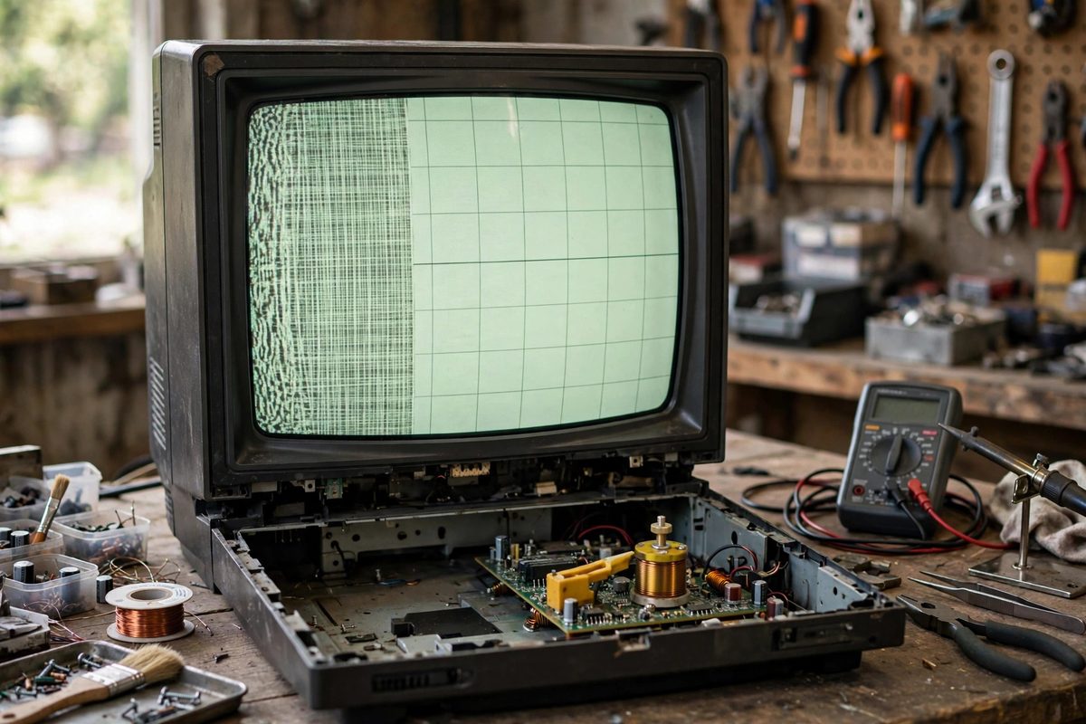
A classic Sony Trinitron with stretched or compressed picture geometry on the left or right side of the screen often needs its horizontal linearity coil adjusted. This small adjustable inductor in the horizontal deflection circuit compensates for the nonlinear way the electron beam sweeps across the flat-ish Trinitron tube. Tuning it is a delicate adjustment inside a live high-voltage chassis, so it belongs to technicians who understand the risks.
What Horizontal Linearity Means
In a CRT, the electron beam is swept horizontally by a sawtooth current in the deflection yoke. Ideally, equal increments of time produce equal increments of horizontal position, so a test pattern of evenly spaced vertical lines looks even across the screen. In practice, the inductance of the yoke and the characteristics of the tube make the sweep slightly nonlinear: the beam may move faster at one side of the screen than the other, stretching the picture on one side and compressing it on the other. The linearity coil is an adjustable inductor placed in series with the horizontal deflection circuit; changing its inductance reshapes the sweep current to compensate. On Trinitrons, whose aperture grille tubes have their own geometry quirks, this adjustment is part of the standard setup procedure.
Recognizing a Linearity Problem
Display a crosshatch or dot test pattern and look at the spacing of the vertical lines. If the lines bunch together on the left and spread apart on the right, or vice versa, that is a linearity error rather than a width or centering error. Width problems change the overall size symmetrically; linearity problems change the spacing asymmetrically. Confirm the set is warmed up fully before judging, since geometry drifts as the chassis reaches operating temperature. Also rule out magnetized shadow mask issues or yoke positioning problems, which produce different symptoms like color purity errors or trapezoidal distortion. Adjusting linearity to compensate for a different fault just creates two problems.
The Adjustment Procedure
Locate the horizontal linearity coil on the main board using the service manual for the specific chassis; it is typically a small coil with an adjustable slug or a movable magnet. With the set running and displaying the test pattern, adjust the coil in small increments and watch the line spacing even out. Work slowly, because the interaction with the horizontal width and hold means each adjustment shifts things slightly. The goal is uniform spacing across the full width, accepting that the extreme edges of a consumer Trinitron will never be geometrically perfect. If the coil's adjustment range cannot correct the error, the coil itself may have failed, or a capacitor in the horizontal circuit may have drifted; do not force the adjustment past its range.
High-Voltage Safety Is Mandatory
A Trinitron chassis contains lethal voltages: the anode runs at tens of thousands of volts, and the horizontal output stage carries high peak voltages even at lower DC levels. Use insulated adjustment tools, keep one hand behind your back, and never reach across the chassis. The linearity coil is on the low-voltage side of the horizontal circuit relative to the anode, but the entire area demands the same discipline. Discharge the tube's anode to the chassis ground before doing any board-level work with the set off, and treat every capacitor in the horizontal section as charged until proven otherwise. If you are not already comfortable working around live high voltage, this adjustment is not the place to learn; find a mentor or a qualified technician.
When Adjustment Is Not Enough
Some geometry errors come from component aging rather than misadjustment. Capacitors in the horizontal deflection circuit drift with age and heat, changing the sweep waveform in ways the linearity coil cannot fully correct. A linearity problem that appears gradually over years, or one that the coil can only partially fix, points to tired components. Replacing the relevant capacitors with correct modern equivalents often restores the geometry to what the coil can then fine-tune. Also check for cracked solder joints around the horizontal section, since thermal cycling works joints loose and intermittent connections produce geometry that wanders. Fix the underlying fault first, then set the linearity.
The horizontal linearity coil exists to make the sweep uniform across the Trinitron's width. Diagnose with a test pattern, adjust in small steps with proper high-voltage discipline, and look to aging components when the coil's range runs out. Geometry this good is worth the care.
Related Guides
- Discharging Anode Voltage on CRT Monitor Tubes: A CRT monitor tube stores a dangerous charge on its anode, the high-voltage connection under the suction-cup cap on the side of the tube, even after
- Flyback Transformer Arcing and Corona Rings: The flyback transformer in a CRT television generates the high voltage, typically 20,000 volts or more, that accelerates the electron beam. At those
- Discharging Ultor Anode Voltage on Color CRT Tubes: A color CRT holds a lethal charge on its ultor anode long after the set is unplugged, tens of thousands of volts waiting under the suction-cup