
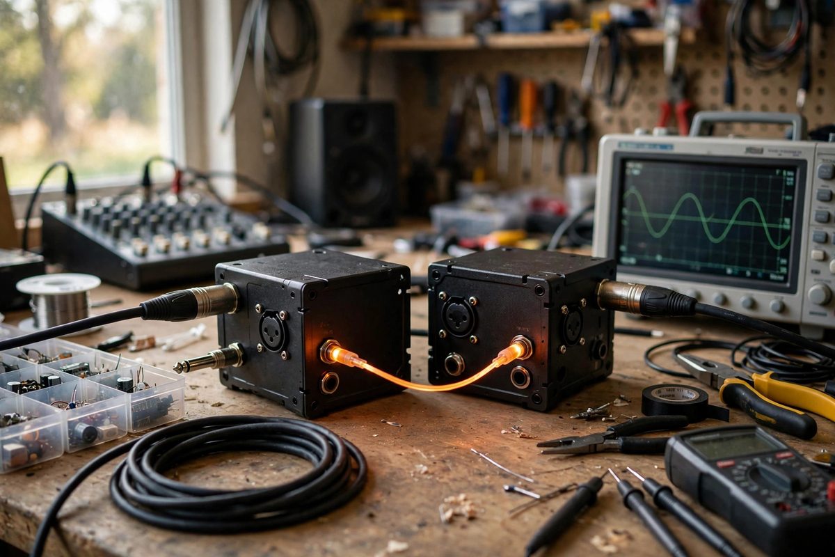
Ground loop hum is the fifty or sixty hertz drone that appears when two pieces of gear share more than one path to ground. It is the most common noise problem in sound rigs, and the most misunderstood. Optical isolation in a line-level DI box breaks the loop completely by converting the signal to light and back, so the two sides never share an electrical connection at all.
How Ground Loops Form
Any time two devices connect through both a signal cable shield and their own mains grounds, a loop exists. The loop acts as an antenna for mains fields, and the tiny voltage it picks up gets amplified as hum. The classic case is a laptop running on its charger feeding a mixer that is grounded through the PA: the audio cable shield and the two power cords form a big loop right through the equipment. Lifting the shield at one end can break it, but that sacrifices the shielding the cable was providing. A proper isolation device breaks the ground path while keeping the signal path intact.
Why Optical Isolation
Most DI boxes isolate with a transformer, which works well but has limits: transformers pass some capacitive coupling, they can saturate at low frequencies and high levels, and cheap ones color the sound. An optical isolator converts the audio to light inside an optocoupler, transmits it across a physical gap with no electrical connection whatsoever, and converts it back. There is no shared ground, no shared conductor, no capacitive path, nothing. The isolation is essentially total across the audio band. The tradeoff is circuit complexity and power needs, since the optical stage needs clean local power on each side.
Line Level Versus Instrument Level
Line-level signals from mixers, playback devices, and keyboards are hotter and lower impedance than instrument signals, and the DI must handle that without distortion. A line-level optical DI is designed for those levels, with headroom to spare for hot outputs and the input impedance to avoid loading the source. Using an instrument DI on a line source risks clipping the input stage; using a line DI on a passive guitar pickup loads it down and kills the tone. Match the box to the signal level and the isolation does its job transparently.
Building or Buying for Your Rig
Commercial optical isolators exist but are less common than transformer DIs, and DIY builders have an edge here because the circuit is straightforward: a clean input buffer, the optocoupler stage with proper biasing, and a clean output driver, each side powered independently. The critical design points are linearity of the optical transfer and low distortion at both ends of the level range. Whatever route you take, verify with a loopback test: feed a quiet signal through with the grounds deliberately looped, and listen for hum with the isolator in and out. The difference should be dramatic and immediate.
Placement in the Signal Chain
Put the isolator at the boundary between the two grounded systems, which is usually right where the cable leaves one device for the other. In a live rig, that often means at the mixer input for playback sources or at the stage box for backline feeds. One isolator per loop is the rule; stacking multiple isolators in series gains nothing. And remember that optical isolation fixes ground loops, not all noise: RF interference, dirty power, and bad cables have their own cures, and no isolator fixes a broken shield.
When hum comes from a ground loop, breaking the loop is the cure, and optical isolation breaks it absolutely. Match the level, power each side cleanly, place the box at the system boundary, and the hum disappears because the loop no longer exists.
Related Guides
- Ground Lift Switch Circuit Isolation for Stage DI Boxes: A ground lift switch is one of the most-used and least-understood controls on a stage DI box. It exists to break ground loops, the humming menace
- Balanced XLR Ground Pin Wiring to Stop Ground Loops: The hum that appears when you connect two pieces of audio gear together, and vanishes when you disconnect them, is almost always a ground loop: an
- Acoustic Reflection Baffles for Stage Backdrops: A stage backdrop is usually designed for the eyes, but it is also a giant acoustic surface that shapes what the audience hears. A flat, hard backdrop
- Star Grounding Buses for High Gain Preamp Racks: High-gain preamps amplify everything, including the tiny voltage differences between ground points in the chassis. When grounds connect in a daisy
- Diffuser Splay Angles for Acoustic Stage Panels: Stage sound is a battle between clarity and chaos: the performers need to hear each other, the audience needs to hear the performers, and the room's