
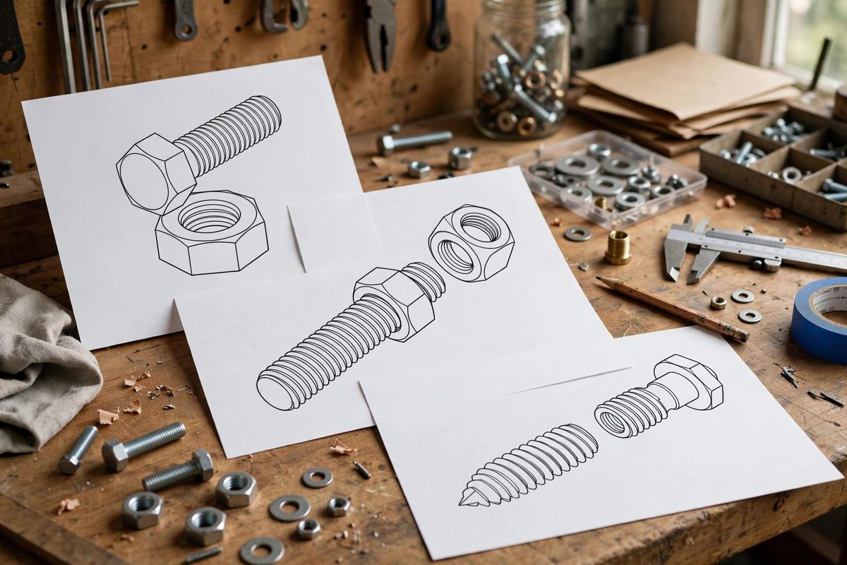
Assembly manuals live or die on their drawings. When a manual needs to show how threaded fasteners go together, the drawing has to communicate the thread's form, the engagement direction, and the assembly order at a glance. Isometric thread profiles, stylized but accurate representations of screw threads in 3D-ish views, are the workhorse graphic for the job.
Why isometric for assembly steps
Isometric projection shows three faces of a part at once, which is exactly what an assembler needs: they can see the thread, the head, and the mating hole in one view without mentally rotating the part. Orthographic views are more precise for manufacturing but slower to read for assembly; a flat side view of a screw tells you its length but not how it sits in the hole. Manuals serve assemblers, not machinists, so the drawing should prioritize instant readability over dimensional completeness.
Drawing the thread profile
A true thread helix is fiddly to draw by hand, so manuals use conventions. The standard approach is a series of evenly spaced diagonal lines or a simplified zigzag representing the thread crests, drawn at the isometric angle of the part's axis. Keep the profile consistent: same spacing, same depth, same angle on every screw in the manual. For the common V-thread, the zigzag reads instantly as "threaded" without anyone needing to measure the pitch. What matters is that the reader recognizes a threaded part and can distinguish it from a smooth pin or a press-fit dowel.
Showing engagement and direction
The thread profile alone does not show which way the screw turns or how far it goes. Add a curved arrow near the head indicating the tightening direction, and show the screw at the correct stage of engagement for that step: hovering at the hole mouth, half driven, or fully seated. Exploded views with the screw floating on the assembly axis are the clearest way to show order when several fasteners go into one joint. Number the fasteners in the order they should be driven when sequence matters, such as star patterns on flanges.
Consistency across the manual
Pick one visual language for threads and use it everywhere. If screws are drawn with the zigzag profile in step three, they should not be smooth cylinders in step twelve. Build a small library of fastener symbols at the manual's scale: the common screws, bolts, nuts, and washers the kit uses, each drawn once and reused. Consistency lets the reader stop decoding the drawing style and focus on the assembly, which is the whole point of the manual.
Print realities: line weight and reproduction
Printed manuals get photocopied, scanned, and read under bad light. Thread profiles drawn with hairline strokes vanish in reproduction; use line weights that survive a copy of a copy. High contrast matters more than fine detail. Test the manual by photocopying it at the cheapest settings you can find and checking that every thread still reads as a thread. A drawing that only works on the original screen file is not a manual illustration.
Pairing drawings with minimal text
The best assembly manuals let the drawings carry the meaning and keep text to labels, warnings, and torque values. A short callout naming the fastener size next to the isometric view covers identification; the drawing covers the how. Resist the urge to describe in a paragraph what the drawing already shows. Fewer words also mean easier translation when the manual ships to other languages.
Draw threads in isometric with a consistent simplified profile, show the engagement stage and direction, keep the line work copy-proof, and let the pictures do the talking. The manual that reads at a glance assembles without mistakes.
Related Guides
- Isometric Projection Layouts for Shop Guides: A shop guide lives or dies on its drawings. Isometric projection, the 3D drawing method where all three axes are drawn to the same scale at 120
- Section Cut Hatch Patterns in Shop Assembly Blueprints: A section view cuts through an assembly to show its insides, and hatch patterns, the diagonal lines filling the cut surfaces, are what tell the
- Section Hatch Pattern Standards for Technical Prints: Cut a part open on a drawing and the exposed faces get hatched: the diagonal lines that say this material is solid here. Section hatching looks like
- Section Hatch Pattern Conventions on Machine Prints: A section view cuts an imaginary slice through a part to show its hidden interior, and the hatch pattern, the diagonal lines filling the cut faces