
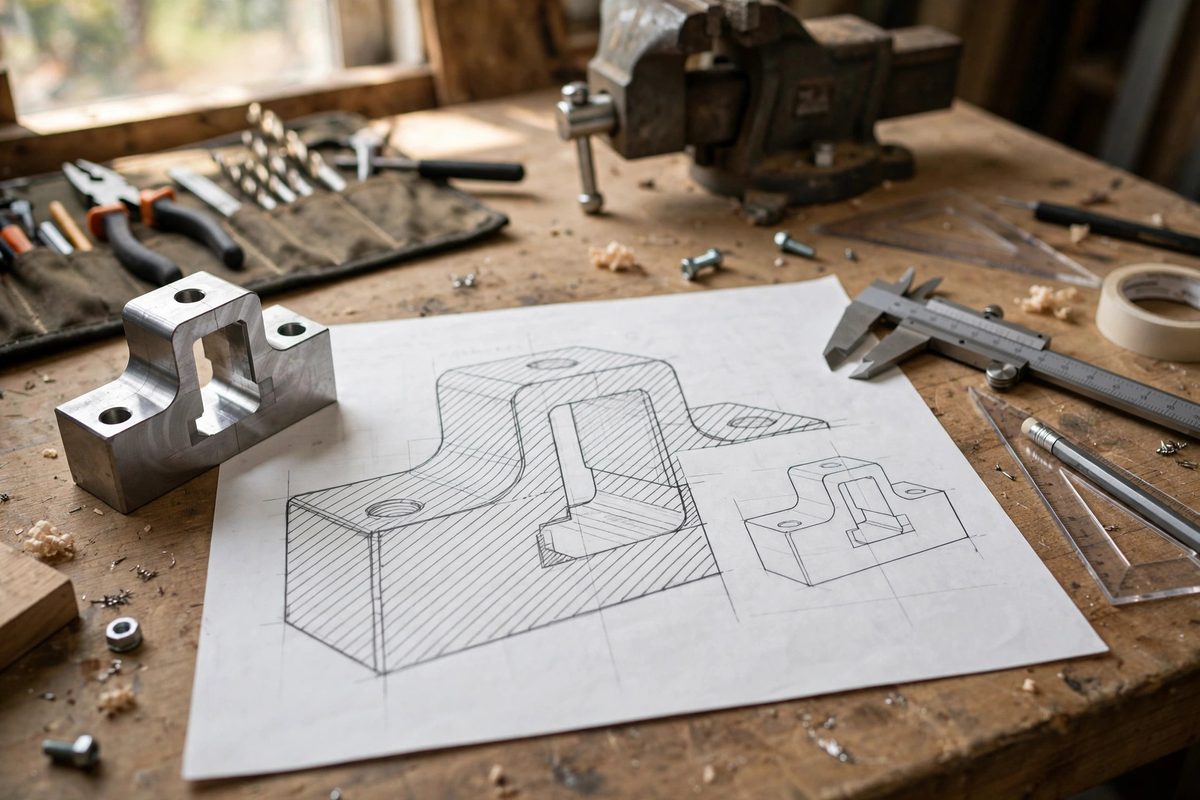
Cut a part open on a drawing and the exposed faces get hatched: the diagonal lines that say this material is solid here. Section hatching looks like mere decoration until you try to read a print where it is done wrong, and then you discover it carries real information. The pattern identifies materials, distinguishes adjacent parts, and reveals the internal structure that the section view exists to show. Standards govern the patterns so that any trained reader extracts the same meaning. This guide covers the conventions that make section views unambiguous.
What hatching communicates
Hatching serves three purposes at once. First, it marks which areas of the view are cut material as opposed to empty space or uncut surfaces visible beyond the cutting plane. Second, the specific pattern can identify the material: the general-purpose diagonal hatch means any material, while standardized special patterns denote common materials like steel, cast iron, copper alloys, and nonmetals. Third, when several parts meet in an assembly section, differing hatch angles distinguish one part from another, so the reader can trace each component through the view. A section view without correct hatching is a puzzle; with it, the internal arrangement reads at a glance. The lines are small, but the information density is high.
The general-purpose hatch
The default section hatch is a set of evenly spaced thin diagonal lines, typically drawn at forty-five degrees to the part's principal outlines. Forty-five degrees is the convention because it rarely coincides with the part's own edges, which would create visual confusion; when a part's edges do run near forty-five degrees, the standard allows shifting to thirty or sixty degrees for clarity. Spacing should be uniform and proportionate to the size of the hatched area: large areas get wider spacing, small areas tighter, but always even. The lines are thin relative to the visible outlines, establishing a clear visual hierarchy where the part's shape dominates and the hatching supports. Draw the hatch to fill the cut area completely, stopping cleanly at the boundary lines.
Material-specific patterns
Beyond the general hatch, established standards define patterns for common material families. Cast iron traditionally gets a widely spaced pattern sometimes doubled, steel gets the standard diagonal, nonferrous metals and nonmetals have their own variants, often with the diagonal lines supplemented by dots, crosses, or wavy elements. In modern practice, many shops simply use the general-purpose hatch for everything and identify materials in the title block or parts list, which is acceptable when the drawing's material callouts are complete. The special patterns earn their keep in assembly sections with multiple materials, where pattern differences let the reader identify each part's material without cross-referencing the parts list for every component. Whichever approach you use, be consistent within the drawing set and make sure the title block or notes define any non-obvious usage.
Hatching assemblies
Assembly sections are where hatching discipline matters most. Adjacent parts must be hatched at different angles so the boundary between them is unmistakable; the convention is to alternate forty-five degrees one way and forty-five degrees the other for neighboring components. The same part appearing in multiple places in one view keeps the same hatch angle and spacing throughout, which lets the reader recognize it everywhere it appears. Thin parts in section, such as gaskets or shims, may be shown solid black instead of hatched when they are too thin for lines to read. Do not hatch areas that are not actually cut by the section plane, no matter how tempting it is to emphasize them; hatching means cut material, and using it otherwise corrupts the language.
Common errors and how to avoid them
A few mistakes recur in student and hobby prints. Hatching at the same angle on adjacent parts merges them visually into one component, defeating the section's purpose. Inconsistent spacing looks unprofessional and can suggest material differences that do not exist. Hatching across a visible outline that is not a cut boundary misrepresents the geometry. And the subtlest error: changing a part's hatch angle between views, which breaks the recognition that consistent hatching provides. The prevention for all of these is the same: hatch deliberately, part by part, checking each hatched region against the questions, is this cut, which part is this, and does its pattern match that part everywhere. CAD systems automate the line-drawing but not the decisions; the operator still chooses the angles and must still verify them.
Teaching the conventions
Hatching is an ideal topic for hands-on instruction because the feedback is immediate. Give students an unhatched assembly section and the standard patterns, and have them hatch it, then compare results: disagreements about which angle goes where surface the conventions naturally. Include at least one tricky case, such as a thin gasket or a part whose edges run at forty-five degrees, to force engagement with the exceptions. Emphasize that these are communication standards, not artistic choices; the point is that a machinist who has never met the drafter reads the same part from the drawing. In an era of 3D models, 2D sections remain the legal and practical definition of many parts, and hatching remains part of that language.
Section hatching is a small vocabulary with large meaning: forty-five-degree thin lines for cut material, varied angles to separate adjacent parts, consistent patterns to identify each component, and material patterns where they add clarity. Learn the conventions, apply them deliberately, and your section views will say exactly what you mean to every reader.
Related Guides
- Section Hatch Pattern Conventions on Machine Prints: A section view cuts an imaginary slice through a part to show its hidden interior, and the hatch pattern, the diagonal lines filling the cut faces
- Section Cut Hatch Patterns in Shop Assembly Blueprints: A section view cuts through an assembly to show its insides, and hatch patterns, the diagonal lines filling the cut surfaces, are what tell the
- Isometric Projection Layouts for Shop Guides: A shop guide lives or dies on its drawings. Isometric projection, the 3D drawing method where all three axes are drawn to the same scale at 120
- Isometric Thread Profiles for Printed Assembly Manuals: Assembly manuals live or die on their drawings. When a manual needs to show how threaded fasteners go together, the drawing has to communicate the