
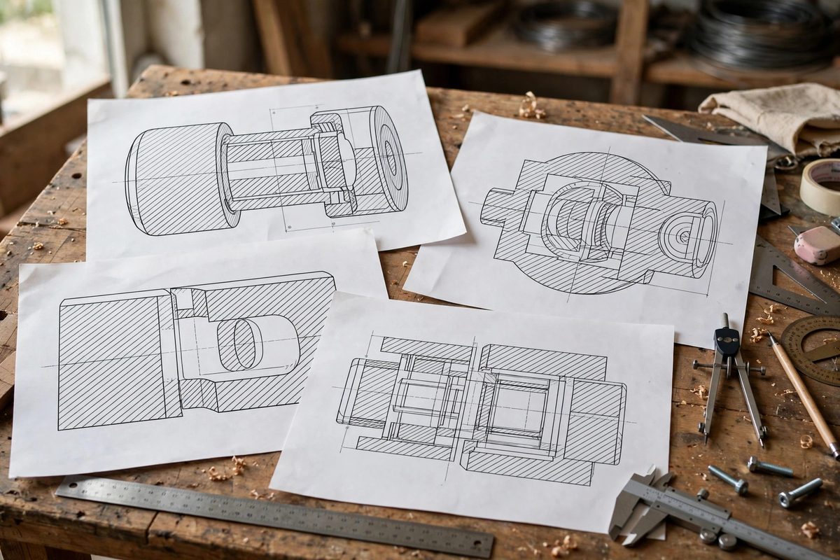
A section view cuts through an assembly to show its insides, and hatch patterns, the diagonal lines filling the cut surfaces, are what tell the reader which parts are solid, which are which, and how they relate. In shop blueprints for makers, where the reader is also the builder, clear hatching prevents the misreadings that waste material: confusing two adjacent parts as one, missing a hidden component, or misjudging a fit. Hatching follows conventions that are simple to learn and costly to ignore.
What Hatching Communicates
Hatch lines mark the surfaces exposed by the imaginary cut: where the cutting plane slices through solid material, hatching appears; where it passes through empty space, nothing appears. This single rule lets a reader reconstruct the 3D assembly from the 2D view: hatched regions are material, unhatched regions within the outline are voids, passages, or spaces. The angle and spacing of the hatch lines then identify the parts: adjacent parts get different hatch angles so the boundary between them reads clearly, and the same part hatched in multiple views keeps the same angle, establishing its identity across the drawing set. A section view without proper hatching is just an outline with confusing interior lines; with proper hatching, the construction becomes legible at a glance.
Standard Patterns and Their Meanings
The general-purpose hatch is a set of evenly spaced diagonal lines at 45 degrees: this means "solid material, no special designation," and it covers most maker blueprint needs. Adjacent parts in the same section get the same pattern at different angles, commonly 45 degrees one way for the first part and 45 degrees the other way, or 30/60 degrees, for its neighbor, so the mating surfaces are visually distinct. Thin parts in section, like gaskets or shims, are often shown solid black instead of hatched, because hatch lines at readable spacing would not fit; this is a standard exception worth knowing. Assemblies with many parts cycle through additional angles and spacings, and very large hatched areas may use a sparser spacing to avoid a visually heavy drawing. The key discipline is consistency within the drawing set: once a part has a hatch identity, it keeps it everywhere.
Hatching Adjacent Parts in Assemblies
Assembly sections live or die on part distinction. When two parts meet at a mated surface in the section view, their hatch angles must differ clearly: identical angles on both sides of a joint line make the joint invisible, and the reader cannot tell where one part ends and the other begins. This matters practically: a builder reading the print needs to see that the shaft and the hub are separate parts with a fit between them, not one piece. For three or more parts meeting, use three distinct angles, and if the assembly is complex, add a parts list keyed to the hatch identities. Pay special attention where a fastener passes through parts: the fastener gets its own hatch angle, and the clearance around it reads as unhatched space. The section should answer "how many parts am I looking at and how do they stack" without the reader having to study it.
What Not to Hatch
Conventions exclude certain elements from hatching even when the cutting plane passes through them, and these exceptions prevent clutter. Standard fasteners, bolts, screws, pins, shafts, and similar solid-of-revolution parts are not hatched when cut lengthwise: their familiar outlines read clearly without hatching, and hatching them adds visual noise. Thin features like webs and ribs are not hatched when the cutting plane passes along their length, because hatching would falsely suggest massive material where there is only a thin stiffener; they are shown in outline. These exceptions have a rationale: hatching marks material to aid understanding, and where the geometry is already unambiguous, hatching subtracts clarity. Learn the exceptions because misapplying hatching to a shaft or rib is the mark of a drawing made without knowledge of the conventions, and it confuses experienced readers.
Drawing Hatching for Shop Use
For maker blueprints, legibility beats drafting perfection. Keep hatch spacing generous enough to read at the print's actual size: hatching drawn for a large screen becomes a gray blur when printed on letter paper. Use consistent line weight, lighter than the object outlines, so the hatching supports rather than competes with the geometry. In CAD, use the hatch tools but verify the result: automatic hatching occasionally fills the wrong regions on complex outlines, and a few seconds of checking prevents a misleading print. For hand-drawn shop prints, a 45-degree triangle guides consistent angles, and slight irregularity in spacing is acceptable; the information is in the angle differences and the presence of hatching, not in drafting-machine precision. Label the section clearly with the cutting plane indicators on the parent view, so the reader knows exactly where the cut was taken.
Section hatching is a visual language with a small vocabulary: hatched means cut material, angle changes mean different parts, and the standard exceptions keep it readable. Use it consistently in shop blueprints and the builder sees the assembly's insides as clearly as the designer imagined them.
Related Guides
- Section Hatch Pattern Standards for Technical Prints: Cut a part open on a drawing and the exposed faces get hatched: the diagonal lines that say this material is solid here. Section hatching looks like
- Section Hatch Pattern Conventions on Machine Prints: A section view cuts an imaginary slice through a part to show its hidden interior, and the hatch pattern, the diagonal lines filling the cut faces
- Isometric Thread Profiles for Printed Assembly Manuals: Assembly manuals live or die on their drawings. When a manual needs to show how threaded fasteners go together, the drawing has to communicate the
- Isometric Projection Layouts for Shop Guides: A shop guide lives or dies on its drawings. Isometric projection, the 3D drawing method where all three axes are drawn to the same scale at 120