
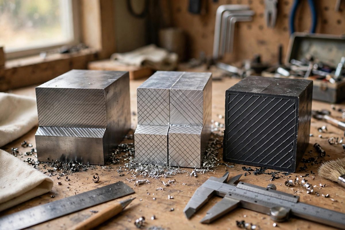
A section view cuts an imaginary slice through a part to show its hidden interior, and the hatch pattern, the diagonal lines filling the cut faces, is what tells the reader which material got cut. Get the hatching right and a machinist reads the print at a glance; get it wrong and the same print causes confusion, wrong material orders, or scrapped parts. The conventions are simple, stable, and worth learning exactly.
What Hatching Communicates
Hatch lines mark the surfaces where the cutting plane passed through solid material. Empty space, holes, and slots that the plane passes through are left unhatched, which is precisely what makes the interior geometry readable: hatched areas are solid, blank areas are air. The pattern of the hatching identifies the material, so a reader can distinguish, say, a steel shaft from a brass bushing inside an assembly section without hunting for a note. Hatching is a language, and like any language it only works when everyone uses the same vocabulary.
The Standard Patterns by Material
The general-purpose pattern, used for most metals including steel and cast iron when no more specific pattern is required, is evenly spaced diagonal lines at 45 degrees. This is the default: when in doubt, use it. Beyond the default, long-established patterns exist for common materials: cross-hatching (two sets of diagonals) for certain treatments, widely spaced lines for concrete, wood shown with grain-like lines following the material's structure, and distinctive patterns for materials like rubber, insulation, and liquids. Adjacent parts in an assembly section get different hatch angles or patterns so the boundary between parts is visible: if two touching parts used identical hatching, the reader could not tell where one ended and the other began.
Angles, Spacing, and Line Weight
Hatch lines are thin compared to the visible outlines of the part: they should read as texture, not as geometry. The standard angle is 45 degrees to the part's principal axes, but when a part's own edges run at 45 degrees, shift the hatch to 30 or 60 degrees so the hatching stays distinguishable from the outline. Spacing should be uniform and proportional to the area: large areas get wider spacing, small areas get tighter spacing, but never so tight the hatching becomes a solid fill. Keep the spacing consistent within a single part, and make sure hatch lines stop cleanly at the part boundaries without crossing into adjacent parts or into unhatched voids.
Hatching Assemblies and Thin Parts
Assembly sections have special rules. Each separate part gets its own hatch angle, typically alternating 45 degrees one way and 45 degrees the other for adjacent parts, so every part boundary is obvious. The same part appearing in multiple places in one view keeps the same pattern throughout, which helps the reader track it. Very thin parts, like gaskets or shims, are often shown solid black instead of hatched, because hatch lines would merge into a blob at that scale; leave a thin white gap between a solid-black thin part and its neighbors so the layers stay readable. Fasteners, shafts, and other standard parts are conventionally left unsectioned (not hatched) when the cutting plane runs along their axis, which keeps assembly drawings from becoming a thicket of lines.
Common Hatching Mistakes
The most frequent errors are easy to avoid once you know them. Hatching a hole or slot that the cutting plane passes through, which falsely shows solid material where there is air. Using the same angle on adjacent parts, hiding the boundary between them. Hatching at 45 degrees on a part whose edges are also at 45 degrees, making the pattern disappear into the outline. Inconsistent spacing that makes one part look denser, and therefore different, from an identical part elsewhere. And forgetting that hatch patterns are a communication tool: adding a legend or material note when using non-standard patterns, so the reader is never guessing.
Why the Conventions Still Matter
In an era of 3D models, it is tempting to treat 2D print conventions as legacy. But prints remain the contract document in most shops: the model may show the shape, but the print with its sections, hatching, and notes is what the machinist works from and what inspection checks against. Correct hatching costs nothing and prevents the most basic misreading of a drawing. For students and self-taught makers, learning these conventions is also a literacy issue: the ability to read anyone's print, not just your own CAD output, is what makes you employable in a real shop.
Hatch the cut faces, leave the voids blank, give adjacent parts different angles, and respect the thin-part and fastener conventions. It is a small discipline, but it is the difference between a drawing that speaks clearly and one that mumbles.
Related Guides
- Section Hatch Pattern Standards for Technical Prints: Cut a part open on a drawing and the exposed faces get hatched: the diagonal lines that say this material is solid here. Section hatching looks like
- Section Cut Hatch Patterns in Shop Assembly Blueprints: A section view cuts through an assembly to show its insides, and hatch patterns, the diagonal lines filling the cut surfaces, are what tell the
- Isometric Projection Layouts for Shop Guides: A shop guide lives or dies on its drawings. Isometric projection, the 3D drawing method where all three axes are drawn to the same scale at 120
- Isometric Thread Profiles for Printed Assembly Manuals: Assembly manuals live or die on their drawings. When a manual needs to show how threaded fasteners go together, the drawing has to communicate the