
Many shop machines speak metric while the project speaks imperial, or the reverse. A conversion dial chart, a circular slide-rule-style reference that turns dial divisions into real measurements, lives on the machine and ends the mental math. Laying one out well makes it a tool; laying it out poorly makes it wall decoration.
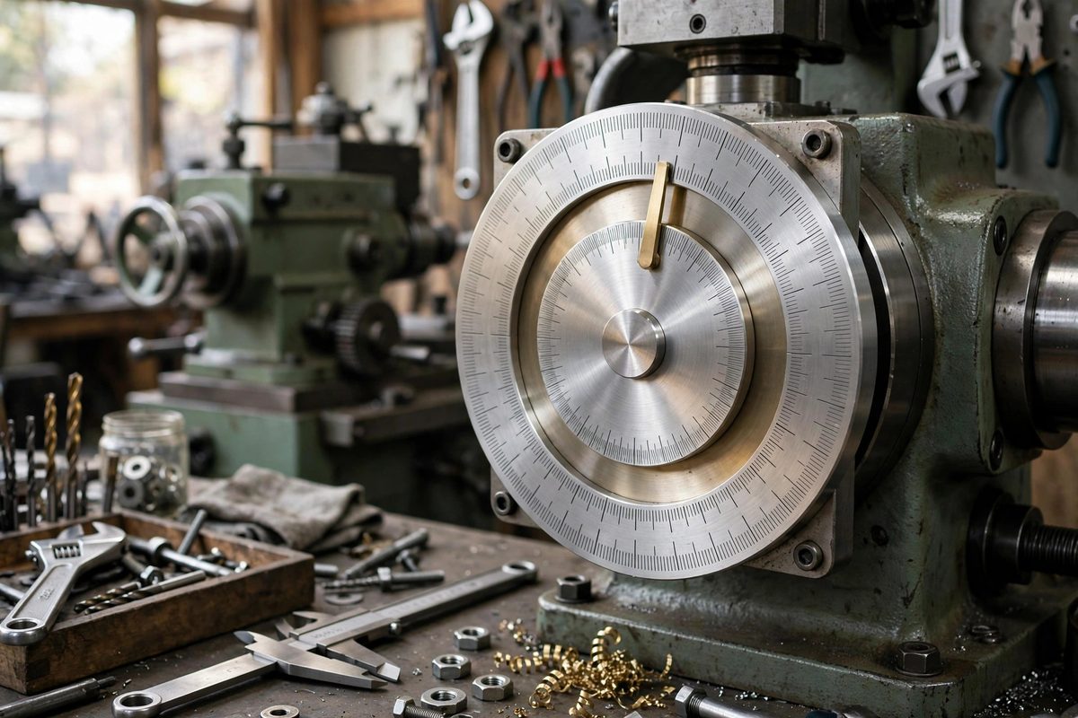
What the chart needs to show
A conversion dial chart maps the machine's dial divisions to actual movement in both unit systems. For a lathe cross-slide with a metric lead screw, the chart shows what each dial division means in millimeters and in thousandths of an inch. The essential data: divisions per revolution, movement per division in native units, and the converted values. Everything else, thread pitches, common conversions, is useful garnish, but the dial mapping is the core. Get that right and prominent; garnish around it.
Layout: readability at arm's length
The chart hangs on or near the machine, read at arm's length in shop lighting, often by tired eyes. Design for that: large type for the primary conversions, high contrast, and a layout that puts the most-used values where the eye lands first. Organize radially or in clear tables; avoid cramming. A chart that requires squinting will not be used, and an unused chart is just paper. Test the layout by printing a draft, hanging it at the machine, and reading it while standing in working position.
Accuracy of the conversions
The conversions must be correct to the precision the machine can actually hold. There is no point printing ten decimal places for a dial that reads to a thousandth; conversely, rounding too aggressively introduces real error over multiple dial turns. Compute the values carefully, double-check the lead screw pitch from the machine's documentation or by direct measurement, and verify a few entries by actually dialing the machine and measuring the movement. The chart is a measuring instrument in paper form; treat its accuracy accordingly.
Durability in the shop
Paper charts die quickly in shops. Laminate the finished chart, or print it on heavy stock and seal it; either way, it should survive oil, coolant mist, and handling. Mount it where it is visible during use but protected from direct spray and chips. A magnetic mount lets it move between machines or come down for cleaning. Plan for replacement: keep the source file so reprinting is trivial when the chart eventually wears out.
Covering the common operations
Beyond the raw dial conversion, include the operations the machine actually performs. For a lathe: diameter versus radius readings, common thread pitches in both systems, and the compound angle settings. For a mill: the conversions for the dials plus common hole spacings. Tailor each chart to its machine; a generic conversion table is available everywhere, but a machine-specific dial chart exists nowhere else. The specificity is the value.
Verification and version control
Mark each chart with the machine it belongs to, the date, and a version note. Machines get modified, lead screws get replaced, and a chart computed for the old screw becomes a liar. When anything about the machine's motion changes, recompute and reprint. Keep the old chart until the new one is verified; a wrong chart is worse than no chart, because it produces confident errors.
Map the dial divisions accurately, lay them out for arm's-length reading, laminate for the shop, tailor to the machine's real operations, and version-control the result. The chart will get used every day, which is the whole point.
Related Guides
- Standard Tap and Drill Clearance Chart Typography: A tap and drill chart is one of the most consulted references in any shop that cuts threads, and also one of the most abused by bad typography. A
- Standardizing Machine Speed Reference Cards for Walls: Every shop with rotating machinery needs the same information within arm's reach: the right spindle speed for the material, the tool, and the
- Standard Machine Tool Feed Charts for Shop Display: Feed and speed charts are the shop wall's quickest reference: glance up, find your material and tool size, and dial in a starting point instead of
- Feed and Speed Reference Charts for Shop Displays: Every shop with a mill, lathe, or drill press needs feed and speed numbers at the point of use, not buried in a handbook across the room. A wall