
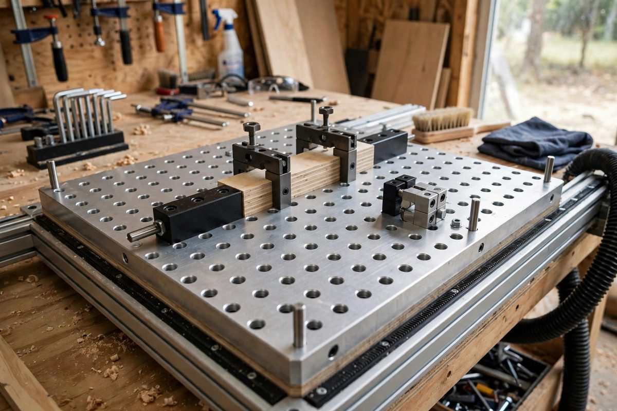
A fixture plate turns a CNC router bed into a universal workholding system: a flat plate drilled with a regular grid of holes that accept clamps, stops, and custom fixtures at repeatable positions. The pitch, the spacing between holes, is the foundational decision, because every clamp, every fixture, and every future accessory must agree with it. Pick a pitch that matches available hardware and your machine's scale. Pick arbitrarily, and every fixture becomes a one-off.
What Pitch Determines
The pitch sets the resolution of your workholding: the smallest increment by which you can reposition a clamp or stop. A fine pitch, holes every inch or so, gives precise positioning for small parts and lets clamps land close to the work. A coarse pitch, every two inches or more, drills faster, weakens the plate less, and suits large work where clamp position is approximate. But pitch also determines compatibility: commercial clamp and fixture hardware is made for specific grid standards, and a plate drilled to a non-standard pitch cannot use off-the-shelf accessories without adapters. The pitch is a commitment: choose it before the first hole is drilled, based on the hardware you intend to use and the size of work you typically run.
Common Standards and Their Logic
Several pitch conventions dominate, each with a rationale. The 1-inch grid is common on smaller machines and 3D-printer-style beds: fine resolution for small parts, and a huge ecosystem of inch-based clamps and stops. The 2-inch (50mm-ish) grid suits mid-size routers: a good balance of resolution and plate strength, with broad hardware support in both inch and metric shops. The 96mm grid comes from the European fixture-plate world and matches a deep catalog of modular fixturing components. The underlying logic in every case is the same: pick the pitch that the hardware you can actually buy is made for. A beautiful plate on a pitch nobody supports is a custom-hardware project forever.
Hole Type: Threaded, Plain, or Both
The grid holes themselves come in flavors, and the choice interacts with pitch. Threaded holes accept bolts directly: versatile, since any bolt becomes a clamp stud, but the threads wear with repeated use and a damaged thread ruins that grid position. Plain holes accept dowel pins for precise location plus separate clamping, which is the classic fixture-plate approach: pins locate, clamps hold. Many plates combine both: a grid of plain dowel holes for location with threaded holes interspersed for clamping, or threaded inserts pressed into plain holes, which gives the convenience of threads with replaceable wear parts. Keep the choice consistent across the whole plate: mixed hole types in no pattern are confusing to set up and error-prone under time pressure.
Plate Material and Thickness
The plate must stay flat under clamping loads and remain flat over years of use. Aluminum tooling plate, cast rather than rolled, is the standard: cast plate is stress-relieved and stays flat, while rolled plate can warp when machined. Thickness matters for thread engagement and stiffness: too thin and threads strip, too thick and the plate eats into your machine's vertical work envelope. A common compromise is around three-quarters of an inch for mid-size routers, giving enough thread depth for real clamping force without sacrificing too much Z height. Steel plates are stiffer and more wear-resistant but heavy and harder to drill; MDF or phenolic plates are cheap and easy to make but wear quickly and move with humidity.
Drilling the Grid Accurately
A fixture plate is only as good as its grid accuracy, and the grid must be drilled accurately relative to the machine's axes, not just internally consistent. The best method is to drill the plate on the CNC router itself: the machine drills each hole at its programmed coordinates, so the grid is automatically square to the machine's motion. Drill undersize first, then ream or tap to final size, because a drill bit wandering slightly in a deep hole is the main source of grid error. Deburr every hole: a raised burr around a hole lifts the workpiece off the plate and destroys the flatness you built the plate to provide. After drilling, verify with a dial indicator or by test-fitting a long straightedge of pins across the grid. An error that grows across the plate indicates a machine calibration issue worth fixing before the plate goes into service.
Living With the Grid
Once the plate is in service, protect the investment. Keep a map of which holes are threaded and which are plain if you mixed types. Replace worn threaded inserts promptly; a stripped hole invites improvised workholding that damages neighboring holes. Cover unused holes when running dusty operations, because packed dust in a threaded hole is nearly as bad as damage. And standardize your fixture designs around the pitch from day one: every custom fixture should mount on the grid without modification, so setup becomes assembly rather than invention. The fixture plate pays for itself in setup time, but only if the grid is treated as the standard it is.
Choose the pitch your hardware supports, drill it accurately on the machine itself, and build every fixture to it. The plate stops being a project and starts being infrastructure the day the grid becomes the assumption everything else is designed around.
Related Guides
- Vacuum Hold-Down Plenum Grid Engineering: A vacuum hold-down table replaces clamps with atmospheric pressure, holding sheet stock flat and immobile across its whole surface while the spindle
- Doweling Alignment Tolerance in Aluminum Fixtures: CNC fixtures locate workpieces repeatably, and dowel pins are the classic locating elements: precise, simple, and cheap. In aluminum fixtures, which
- Expanding Mandrel Collet Fits for Lathe Turning Jigs: Turning jigs on the lathe often need to grip a workpiece by its bore, and the expanding mandrel is the elegant solution: a tapered plug that expands
- Pneumatic Clamp Cylinder Sizing for Sheet Routing: Pneumatic clamps hold sheet stock on a CNC router with speed and repeatability that screws and toggle clamps cannot match, but only if the cylinders