
A deck's posts and beams handle vertical loads naturally, but lateral loads, wind, foot traffic shifting, the occasional enthusiastic gathering, push the structure sideways, and a post-and-beam frame with pinned connections is a mechanism, not a structure, until something resists the sway. Knee braces, diagonal members connecting post to beam at 45 degrees, triangulate the frame and convert lateral sway into axial loads the wood handles well. Sizing and placing them correctly is what keeps a tall deck from feeling like a ship in a swell.
Why Frames Sway
A rectangular frame of posts and beams joined with typical hardware has almost no resistance to racking: push the top sideways and the rectangle shears into a parallelogram, with the connections rotating. The resistance that does exist comes from the connections' rotational stiffness, which for bolts and nails is small, and from any sheathing or decking acting as a diaphragm, which helps in the deck plane but does little for the posts below. Tall decks sway more because the lateral displacement at the top grows with post height for a given rotation at the base. The human perception threshold is low: a deck that moves visibly underfoot feels unsafe long before it is structurally unsound, and perceived safety is part of the design requirement. Knee braces fix the mechanism by triangulation: a diagonal across the post-beam corner makes the rectangle into two triangles, and triangles do not rack.
Knee Brace Geometry
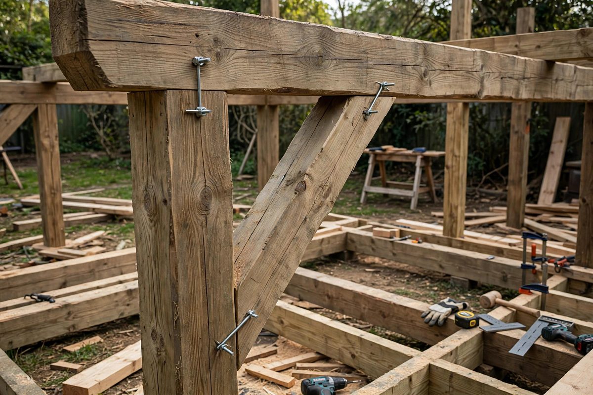
The classic knee brace runs at 45 degrees from the post to the beam, attached a few feet out from the corner on each member. The 45-degree angle is the sweet spot: it resolves lateral loads into equal axial components along the brace, maximizing the triangulation effect for a given brace length. Steeper braces, closer to vertical, do little against lateral loads; shallower braces eat headroom and interfere with the space below. Brace length matters: longer braces engage more of the frame and distribute loads better, but they intrude into the usable space beneath the deck. A common compromise extends the brace roughly two to three feet along each member from the corner. The brace must connect to sound wood on both members, not to the end grain or to a notched section, because the connection is where the triangulated forces concentrate.
Connection Details
A knee brace is only as good as its two connections. Through-bolts are the standard: a bolt through the brace and into the post, and another through the brace and into the beam, with washers spreading the load. The bolts carry the brace's axial loads in shear, and the connection must be detailed so the brace bears firmly against both members without gaps; a gapped connection hammers under cyclic lateral loads and loosens. Avoid relying on nails or screws alone for structural knee braces: their withdrawal and shear capacities in this application are inadequate, and they loosen under the reversing loads that sway produces. Notch the brace into the members or use housed joints where the design allows: a brace seated in a shallow housing cannot slip, and the housing carries some of the load in bearing rather than leaving it all to the bolt. Whatever the detail, both connections must resist forces in both directions, because sway reverses.
Placement Around the Structure
Brace the frame in both lateral directions: braces in the plane of the beams resist sway along the beam direction, and braces perpendicular to that, or the inherent stiffness of a ledger-attached side, handle the other axis. A deck attached to the house with a proper ledger is braced on the house side by the building itself; the outer posts need the knee braces. Freestanding decks need bracing on all sides. Concentrate bracing at the corners and at the tallest posts, where sway is worst. Do not brace only one bent of a multi-bent deck and assume the decking distributes the stiffness: it distributes some, but each bent should stand on its own. For very tall decks, consider bracing at two levels or adding diagonal sheathing to the posts; knee braces alone have practical limits as post height grows.
Limits and When to Engineer
Knee bracing handles typical residential decks within prescriptive rules, but several conditions push beyond them: decks carrying heavy loads like hot tubs, where the mass amplifies lateral forces; very tall decks, where second-order effects magnify sway; decks in high-wind or seismic zones, where the lateral demands are codified and significant; and any deck where the bracing geometry is compromised by openings, stairs, or headroom requirements. In these cases, the prescriptive knee-brace rules do not apply and the lateral system needs engineering: moment frames, engineered shear panels, or foundation-level fixity. The honest assessment is part of the builder's job: knee braces are a proven solution within their scope, and recognizing when the project exceeds that scope is what separates a builder from a gambler.
Knee braces turn a swaying frame into a triangulated structure: 45 degrees, a few feet each way from the corner, through-bolted to sound wood, on every unbraced bent. Size them for the loads, respect their limits, and the deck will stand still underfoot the way it should.
Related Guides
- Fastener Corrosion Limits in Pressure-Treated Rim Sills: Pressure-treated lumber protects against rot and insects, but the preservative chemicals that do the protecting are corrosive to steel fasteners. The
- Ledger Board Fastener Shear Load Spacing: A deck ledger is the board bolted to the house that carries half the deck's weight, and its fasteners carry that weight in shear while resisting the
- Stair Stringer Throat Depth for Exterior Landings: Cut stringers are the backbone of most exterior stairs, and the weakest point of every cut stringer is the throat: the thinnest section of wood left
- Rim Joist Flashing Detail Under Composite Facia Boards: Composite fascia looks crisp on day one and hides a slow problem behind it. Water running off the deck surface finds its way behind the fascia board