
The tuning capacitor is the heart of a vintage radio's dial, and when its gangs fall out of alignment the radio tunes deaf: stations drift, sensitivity collapses at one end of the band, and the dial lies. Realigning a multi-gang air variable capacitor is careful mechanical work, but it restores the tracking that makes the whole band come alive evenly.
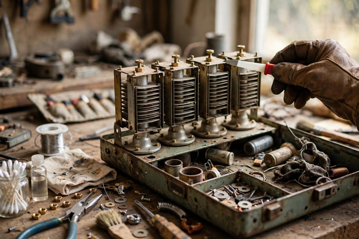
How the Gangs Work Together
A multi-gang capacitor has two or more rotor sections on a common shaft, each serving a different tuned circuit: typically one for the antenna input and one for the local oscillator, sometimes a third for an RF stage. As the shaft turns, all gangs change capacitance together, and the circuits are designed to track, staying at the correct frequency relationship across the whole dial. Tracking depends on each gang's plates being correctly positioned relative to the shaft and to each other. When a radio has been dropped, roughly handled, or "repaired" by an enthusiastic amateur, the gangs no longer track and the radio's performance falls apart unevenly across the band.
Inspecting Before Adjusting
Before touching any adjustment, inspect the capacitor mechanically. Look for bent plates, plates touching each other, loose rotor bearings, and cracked insulators. A bent plate that shorts at one shaft position will never align correctly until it is straightened. Check that the rotor turns smoothly through its full range without binding or wobble; worn bearings let the rotor shift axially, which changes capacitance unpredictably. Clean the plates gently with a soft brush and contact cleaner; decades of grime between plates changes capacitance and can cause noise. Only after the mechanics are sound does alignment make sense.
The Alignment Procedure
Alignment is done with the radio powered and a signal source, following the classic sequence: set the oscillator tracking first, then the RF and antenna stages. At the high-frequency end of the band, adjust the trimmer capacitors, the small adjustable caps in parallel with each gang, for peak response. At the low-frequency end, adjust the coil slugs or the padder capacitor for peak response. Work back and forth between the ends a few times, because the adjustments interact. The goal is even sensitivity across the band with the dial reading correctly, not maximum peak at one spot with dead zones elsewhere.
Plate Bending: The Last Resort
Some capacitors have slotted rotor plates meant to be bent slightly for fine tracking correction at specific dial positions. This is delicate work: bend a tiny amount, recheck, and stop as soon as tracking is acceptable. Over-bending ruins the plate and there is no un-bending it precisely. Many restorers avoid plate bending entirely and accept slightly imperfect tracking, which is an honest tradeoff; a radio that tracks well across ninety percent of the band beats a capacitor destroyed chasing perfection. Document which plates you touched so future work starts from knowledge, not mystery.
Keeping It Aligned
Once aligned, the capacitor needs mechanical stability to stay that way. Tighten any loose mounting hardware, verify the dial cord or drive mechanism does not slip, and keep the radio from the drops and vibration that caused the problem. A drop of appropriate lubricant on the rotor bearings keeps the action smooth without attracting dust. The alignment will hold for years if the mechanics are left alone, which is the real reward for doing the job carefully once.
A tracking capacitor makes the whole dial work as designed: inspect the mechanics, clean the plates, align trimmers at the high end and coils at the low end, and bend plates only as a last resort. The stations will line up where the dial says they are, across the entire band.
Related Guides
- Reforming Electrolytic Capacitors in Tube Radios: A tube radio that has sat silent for decades often has electrolytic capacitors whose internal oxide layer, the dielectric that makes the capacitor
- Replacing Wax Paper Capacitors in Antique AM Receivers: Every antique AM radio contains wax paper capacitors, and after half a century or more, essentially all of them are bad. They leak DC, drift in
- Aligning Intermediate Frequency Transformers: The intermediate frequency (IF) transformers in a vintage superheterodyne radio are the tuned circuits that give the set its selectivity and much of