
A tube radio that has sat silent for decades often has electrolytic capacitors whose internal oxide layer, the dielectric that makes the capacitor work, has degraded from disuse. Powering up such a radio at full voltage can punch through the weakened dielectric, destroying the capacitor violently and sometimes taking the power transformer with it. Reforming rebuilds that oxide layer gradually by applying voltage slowly while limiting current, nursing the capacitor back to health. It is a standard restoration technique, but it demands respect for the high voltages involved and honesty about when a capacitor is beyond saving.
Why electrolytics degrade in storage
An electrolytic capacitor's dielectric is a microscopically thin layer of aluminum oxide grown electrochemically on the foil plates, maintained by the applied voltage during normal operation. In storage with no voltage applied, that oxide layer slowly dissolves back into the electrolyte. The longer the storage and the hotter the environment, the thinner it gets. Apply full working voltage to a degraded capacitor and the current surges through the weak spots, heating the electrolyte; pressure builds, the vent fails or the can ruptures, and the radio fills with acrid smoke. This is why experienced restorers never just plug in a long-dormant tube radio. The capacitors are not necessarily dead; they are unformed, and reforming is the process of regrowing what time dissolved.
The reforming procedure
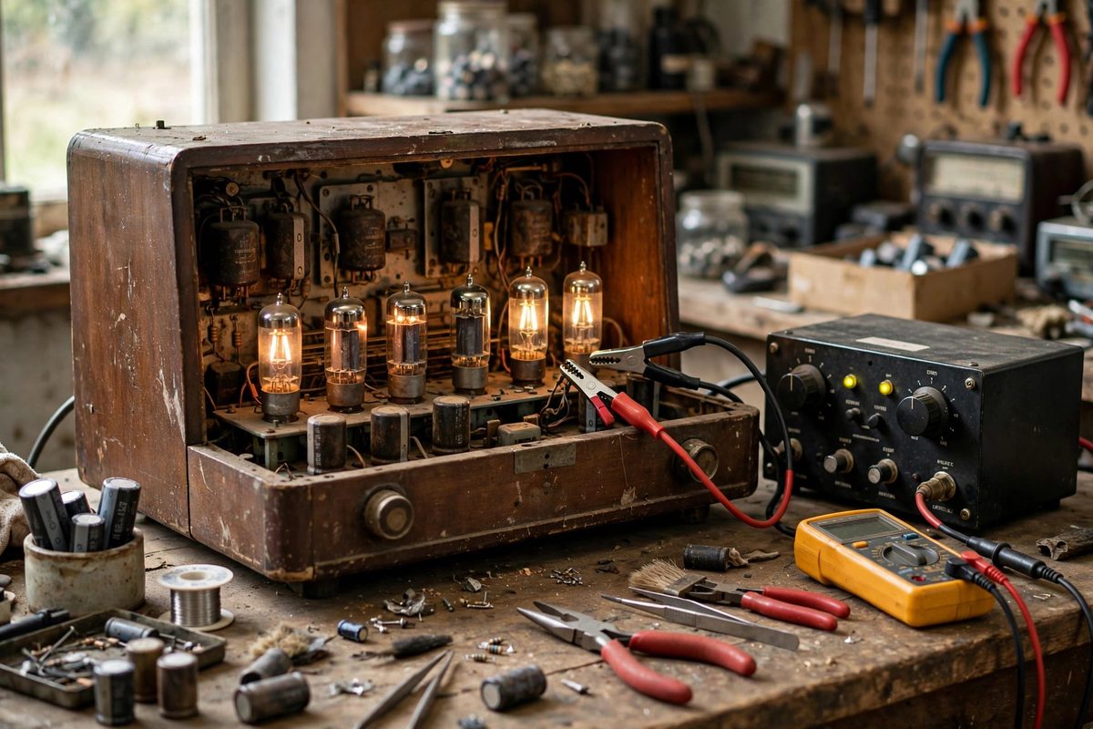
Reforming applies voltage to the capacitor gradually while limiting the current to a safe trickle. The classic method uses a variac to bring the radio's mains voltage up slowly over hours, with a current-limited supply or a series light bulb that drops voltage if current surges. Start low, roughly a quarter of the working voltage, and hold, watching the current: it will start elevated as the oxide rebuilds and should fall to a small leakage value. Then step the voltage up in increments, holding at each step until the current settles. The whole process takes several hours for a typical radio. An alternative is to reform capacitors individually on the bench with a current-limited DC supply before reinstalling them, which gives better control and keeps a failing capacitor away from the radio's irreplaceable transformer. Either way, the principle is identical: voltage low and slow, current limited, patience throughout.
Reading the results honestly
A capacitor that reforms successfully shows falling leakage current at each voltage step and eventually holds full working voltage with only microamps of leakage. That capacitor can go back into service, though wise restorers still consider its age. A capacitor that will not reform announces itself clearly: leakage current that stays high, current that climbs instead of falling, heating, hissing, or any sign of distress. That capacitor is done; replace it. There is no virtue in nursing a capacitor that refuses to reform, because its failure in service will be sudden and may be expensive. The reform-or-replace decision is also philosophical: many restorers replace all electrolytics in a valuable radio as a matter of course, reforming only where originality matters for a museum piece. Both positions are defensible; what is not defensible is plugging in and hoping.
What to replace regardless
Some capacitors should not be reformed at all. Paper and wax capacitors, the tubular kind found throughout tube radios, do not reform; their dielectric degrades permanently and they become leaky, throwing off bias voltages and potentially destroying tubes and transformers. Replace them as a matter of routine, using modern film capacitors of the correct value and adequate voltage rating. Electrolytics in the power supply that show any physical distress, bulging, leaking, or corrosion, get replaced, not reformed. And the line filter capacitor, if the radio has one across the mains, should be replaced with a proper safety-rated type; a failed line capacitor is a shock and fire hazard, not a restoration subtlety.
High voltage safety
Tube radios run B+ voltages of several hundred volts, which is lethally serious. Work with one hand in your pocket when the set is energized, keep the other hand away from the chassis, and use properly rated meter probes. Discharge filter capacitors with a bleeder resistor before touching anything, and verify with a meter; capacitors hold charge after power-off. Use an isolation transformer when working on AC/DC sets with hot chassis, since the chassis itself can be at line potential. Reforming is a slow, calm procedure, and calm is exactly the right temperament for high voltage work. If any of these precautions sounds unfamiliar, stop and learn them from a proper electronics safety reference before proceeding; this article assumes a foundation of high-voltage respect.
Bring the voltage up slowly, limit the current, watch the leakage fall, and replace whatever will not reform. The goal is a radio that plays safely for another few decades, not a heroic rescue of every original component.
Related Guides
- Realigning Multi-Gang Air Variable Tuning Capacitors: The tuning capacitor is the heart of a vintage radio's dial, and when its gangs fall out of alignment the radio tunes deaf: stations drift
- Replacing Wax Paper Capacitors in Antique AM Receivers: Every antique AM radio contains wax paper capacitors, and after half a century or more, essentially all of them are bad. They leak DC, drift in
- Aligning Intermediate Frequency Transformers: The intermediate frequency (IF) transformers in a vintage superheterodyne radio are the tuned circuits that give the set its selectivity and much of