
Every 3D print has a seam: the point where each layer's perimeter starts and stops, leaving a tiny vertical scar. On a box you can hide it in a corner; on a cylinder there are no corners, so the seam sits out in the open as a visible line running up the part. Seam placement optimization is the art of putting that unavoidable scar where it does the least harm, or distributing it so it disappears. On cylindrical shells, where the eye follows the smooth curve and catches any interruption, this matters more than on almost any other geometry.
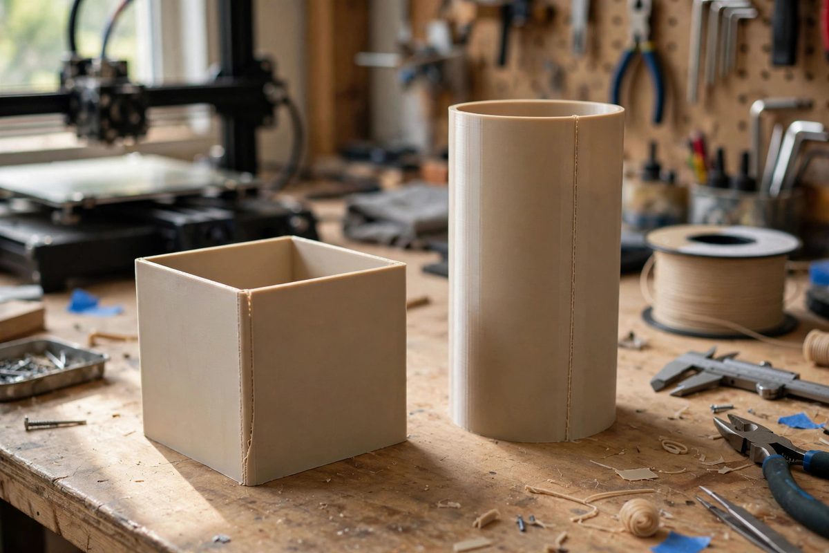
Why Cylinders Expose Seams
A seam is a small blob where the extruder starts the perimeter and a small gap or string where it stops, plus a slight zits-and-divot texture from the pressure change. On flat walls or corners, these defects hide in the geometry: the eye expects a corner to look like a corner. On a smooth cylinder, the surface has no features to camouflage the defect, and worse, the eye is drawn along the curve, so a vertical line of defects reads as a deliberate stripe. The defect is also structurally relevant on thin shells: the start-stop point is where layer adhesion is weakest, and on a pressure vessel or a load-bearing tube, a seam aligned into a continuous vertical line creates a weak axis. Placement is therefore both cosmetic and mechanical.
Rear Placement: The Simple Strategy
The most common approach is to park the seam at a fixed angular position, typically the back of the part relative to its display orientation. Slicers offer an explicit rear or fixed-angle option. This concentrates all the defects into one vertical line, which sounds bad but is actually optimal for display pieces: one faint line at the back beats defects scattered everywhere. The key is choosing the angle deliberately. Consider how the part will actually sit and be viewed: the "back" of a vase on a shelf is the side facing the wall, not an arbitrary slicer default. For functional parts, place the seam where fingers will not constantly feel it and where stress is lowest. The weakness of rear placement is that the aligned seam forms that continuous weak line, so for parts under hoop stress or bending loads, consider the mechanical tradeoff before committing.
Random and Nearest: Distributing the Defect
An alternative is to scatter each layer's seam to a different angular position, either randomly or at the "nearest" point to the previous layer's end. Random placement turns one visible line into dozens of tiny, isolated dots spread around the circumference. From a distance, the surface looks uniformly smooth; up close, you see a faint stipple. This works well for organic or textured parts where no single viewing angle dominates. The cost is print time and surface consistency: random travel moves add time, and the scattered defects can interfere with a perfectly smooth finish if you plan to sand and polish. "Nearest" placement is a compromise that minimizes travel while still breaking up the line, but it can wander into visible clusters on some geometries. Test on a small cylinder before committing to a large print.
Tuning the Seam Itself
Placement decides where the defect sits; tuning decides how bad it is. The main controls are retraction and wipe settings at the layer change, plus any seam-specific gap or overlap compensation the slicer offers. The goal is a start-stop that neither blobs nor gaps: enough material to bond, not so much that it bulges. A small wipe, where the nozzle travels a short distance without extruding at the end of the perimeter, drags the pressure tail away from the seam point. Coasting, stopping extrusion slightly before the end, does similar work. Print a small test cylinder with your candidate settings and inspect the seam under good light, running a fingernail around the circumference: you should feel, at most, a faint tick at the seam. If you feel a distinct bump or a notch, keep tuning before printing the real part.
Designing the Seam Away
The most elegant solution is to design the cylinder so the seam has somewhere to hide. A shallow vertical rib, a decorative groove, a slight facet, or even a deliberate design line gives the slicer a corner to align the seam to, and the feature reads as intentional design rather than a defect. This is standard practice in professional product design: the "parting line" on injection-molded parts is placed along a designed edge. For functional shells, a slightly thicker wall section at the seam location compensates for the weaker bond, addressing the mechanical concern directly. When neither is possible, orient the part so the seam faces away from the primary viewing angle and accept the single faint line as the cost of the geometry.
The seam cannot be eliminated, only managed. Hide it at the back for display pieces, scatter it for organic forms, tune the start-stop until it is a whisper, or design a feature that absorbs it. On cylinders, where there is nowhere to hide by accident, place it there on purpose.
Related Guides
- Scarf Joint Seam Alignment on Precision Cylinders: The seam, where each printed layer starts and stops, is the visible scar on an otherwise smooth 3D print. On precision cylinders, like bearing
- Adaptive Layer Heights for Organic Curves: Organic curves, the smooth domes, fillets, and freeform surfaces on a model, are where fixed layer heights show their weakness. Print a curved
- Coast at End Slicing Settings to Stop Stringing: Stringing, the fine cobwebs of plastic stretching between separate parts of a print, is oozing made visible: molten filament leaking from the nozzle
- Z-Hop Height Tuning to Prevent Thin Wall Collisions: Z-hop lifts the nozzle during travel moves so it does not drag across already-printed plastic, and thin walls are where that protection matters most