
Robot chassis built from aluminum box extrusions are stiff in bending and surprisingly willing to twist, and twist is what ruins precision. A chassis that deflects torsionally under load lets the drive wheels or the arm mounts move relative to each other, which shows up as steering errors, positioning drift, and vibrations that no amount of software tuning can fix. Testing torsional deflection before committing to the design tells you whether the chassis is a rigid platform or a flexible suggestion.
Why torsion is the weak axis
Box extrusions resist bending well because their material sits far from the neutral axis in the bending plane. Torsion is different: twisting a hollow box section stresses the thin walls in shear, and the torsional stiffness depends on the enclosed area and the wall thickness rather than the overall depth. A tall extrusion that is wonderfully stiff as a beam can still twist noticeably when torque is applied about its long axis.
In a robot chassis, torsional loads come from asymmetric drive forces, an arm reaching to one side, or simply the weight distribution when the robot accelerates. The chassis does not need to twist much to cause problems: a fraction of a degree of twist across the wheelbase steers a differential-drive robot off its intended heading, and the error accumulates with distance.
A practical test setup
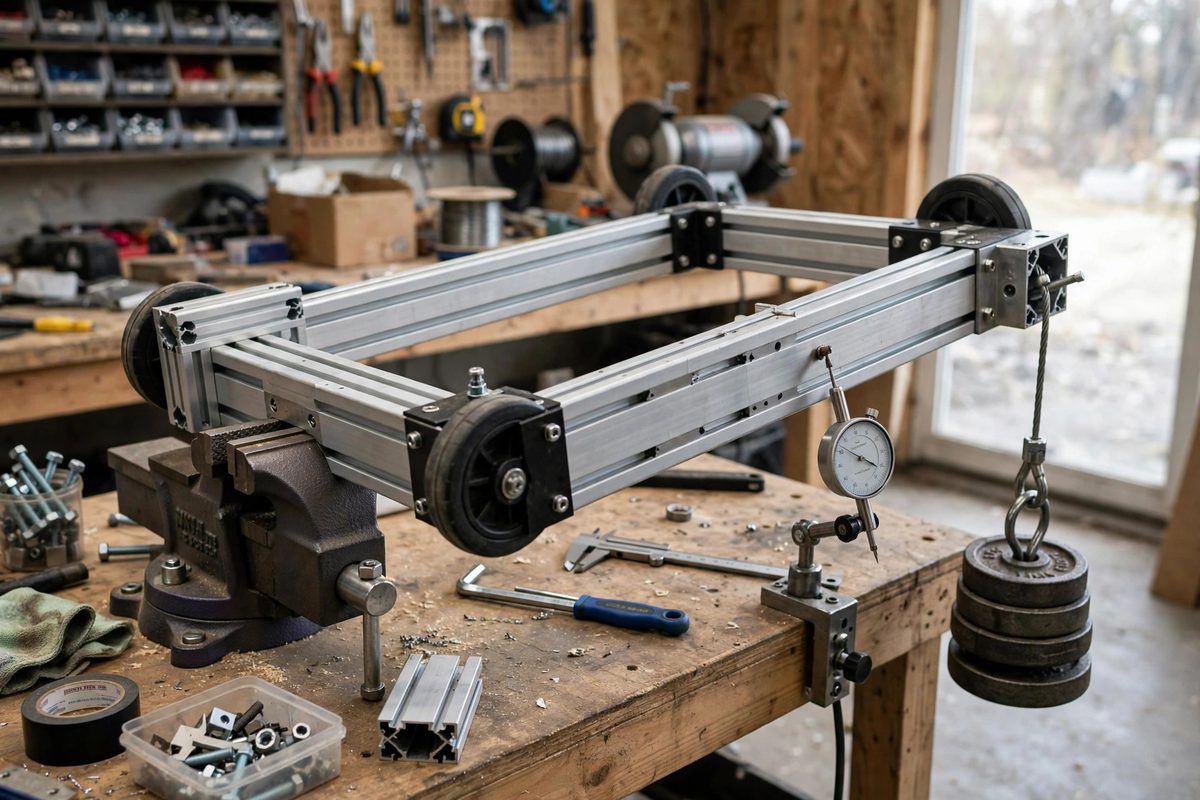
You do not need a metrology lab to measure torsional deflection meaningfully. Clamp one end of the extrusion or the chassis assembly firmly to a rigid bench, taking care that the clamp itself does not flex or allow rotation. Apply a known torque at the free end: a lever arm of known length with a known weight hung from it gives a calculable, repeatable torque. Measure the resulting angular deflection with a dial indicator bearing on a second lever arm, or with a digital angle gauge if the deflection is large enough to read directly.
The key discipline is isolating torsion from bending. The applied load should produce pure torque about the extrusion's long axis, with minimal bending moment. A lever arm perpendicular to the axis, loaded vertically at its end while the extrusion lies horizontally, produces mostly torsion; check that the free end is not also drooping in bending, and correct the measurement if it is.
Interpreting the results
Compute the torsional stiffness as torque divided by angular deflection. Compare it against what the robot needs: estimate the worst-case torsional load from the drive forces or arm loads, multiply by the measured compliance, and see whether the resulting twist is acceptable for the positioning accuracy required. There is no universal threshold; a slow inspection robot tolerates more twist than a precision pick-and-place.
Test the chassis as an assembly, not just as individual extrusions, because the joints dominate. A chassis of stiff extrusions joined by loose corner brackets will twist at the brackets, and the test will show it: the deflection localizes at the joints rather than distributing along the members. If the joints are the weak point, no amount of extrusion upgrading helps; the fix is gussets, through-bolts, or welded corners.
Stiffening strategies that work
When the test shows too much twist, the effective fixes target the torsion load path. Diagonal bracing converts torsional loads into axial loads in the braces, which extrusions resist well; a single diagonal across a rectangular frame bay dramatically increases torsional stiffness. Closing open sections into boxes, adding a shear panel (a thin plate screwed across a frame bay), or upgrading to larger or thicker-wall extrusions in the torsion-critical members all help.
The shear panel deserves emphasis because it is so effective for its weight: a thin aluminum or even plywood panel fastened securely around its perimeter turns a twistable frame into a rigid box. The fasteners must be numerous and tight, since the panel works by carrying shear and every fastener is part of the load path.
Test, stiffen, re-test
After any stiffening change, repeat the test with the same setup and compare numbers. The goal is measured improvement, not theoretical satisfaction. Keep the test rig intact until the design is finalized; you will use it more than once as the chassis evolves.
Clamp it, twist it, measure it, and believe the numbers. A chassis that tests stiff will drive straight; one that was assumed stiff will teach you about torsion at the worst possible moment.
Related Guides
- Torsional Rigidity in 6061 Extruded Frames: Robot chassis built from 6061 aluminum extrusion are easy to assemble and tempting to under-engineer. The failure mode that bites is rarely bending
- Carbon Fiber Tube Gusset Bonding for Quadrupeds: Quadruped robots live on carbon fiber tubes: light, stiff, and easy to source. But tubes alone make a floppy structure; the joints where tubes meet
- Monocoque Carbon Layup Thickness for Robot Pods: A monocoque robot pod, where the carbon fiber shell itself is the structure rather than a skin over a frame, offers the best strength-to-weight ratio
- Triangulated Space Frame Bracing for Tubular Rovers: A tubular rover chassis built from straight tubes and simple joints has a natural enemy: the rectangle. Four tubes joined in a rectangle will fold