
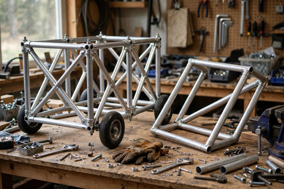
A tubular rover chassis built from straight tubes and simple joints has a natural enemy: the rectangle. Four tubes joined in a rectangle will fold into a parallelogram under the first serious side load, and no amount of thicker tubing fixes it, because the failure is geometric, not material. The fix is triangulation. A diagonal tube across that rectangle turns bending loads into pure tension and compression along the tube axes, which is exactly what round tubing handles best. A chassis braced this way can be dramatically stiffer and lighter than a heavier unbraced one. This guide covers where triangulation matters, how to lay out the diagonals, and the joint details that make or break the whole scheme.
Why triangles beat rectangles
A triangle made of pin-jointed members cannot change shape without changing a member's length, which means loads travel straight down the tubes as tension or compression. A rectangle can shear sideways with its members merely bending at the joints, which puts the tubes into bending, the weakest way to load them. This is the entire structural logic of a space frame: arrange the tubes so every panel is divided into triangles, and the chassis becomes a rigid truss instead of a wobbly cage. The practical consequence for a rover is immediate. Torsional stiffness, the resistance to twisting between the front and rear axles when one wheel climbs an obstacle, comes almost entirely from triangulation of the side and top panels. Skip the diagonals and the chassis twists like a wet noodle no matter how stout the individual tubes are.
Which panels to triangulate first
Not every panel earns its diagonal equally, so brace in order of structural payoff. The side panels carry the bending loads from the suspension and the twisting loads from articulation, so they come first: a diagonal in each side bay transforms the chassis rails from bending beams into truss chords. Next is the floor or belly pan area, which ties the two sides together and resists the lozenging that lets the chassis rack diagonally. The top panel matters if the chassis carries a mast, arm, or payload that applies overturning loads. End panels around the suspension pickups deserve triangulation too, because those joints see the highest concentrated forces on the whole vehicle. A bay that carries no load path can stay open for access, batteries, or wiring. Triangulation is not decoration. Put steel where forces flow and leave the rest open.
Laying out diagonals that actually work
A diagonal is most effective when it runs corner to corner of its bay at something close to forty-five degrees. Very shallow diagonals, running nearly parallel to the chords, carry little load for their weight and mostly add joints. Very steep diagonals approaching vertical do the same. When a bay is long and low, use two diagonals forming an X or a pair of opposing diagonals rather than one long shallow member. Keep the node points clean: diagonals should meet at the same joint nodes as the chords, not land mid-tube. A diagonal welded or clamped to the middle of a chord creates a bending load in that chord at exactly the point you were trying to avoid, undoing much of the benefit. Sketch the frame as a line diagram first and check that every tube end lands on a node shared with other tubes. If your sketch has tubes ending in empty space or mid-span, redraw it.
Joints: where space frames live or die
Triangulation only works if the joints actually transfer the loads, and the joint is where most hobby space frames fall short. A proper node ties all arriving tubes together so forces pass through a common point. Fishmouth the tube ends to fit the mating tube closely, because a gap filled with weld is a stress concentrator, not a joint. With bolted or clamped construction, use gussets or node plates that capture every member; a diagonal held by a single small bolt through thin-wall tube will ovalize its hole under cyclic load and go slack, and a slack diagonal is structurally absent. Whatever the joining method, the test is simple: grab the chassis at opposite corners and twist. Creaking, clicking, or visible joint movement means the nodes are not doing their job, and no tube upgrade will compensate.
Tubing choice and weight discipline
Because triangulated members work in tension and compression, thin-wall tubing performs far better than intuition suggests. The stiffness of the frame comes from the geometry of the truss, while the tube walls mainly need to resist local buckling under compression. Going up a diameter while keeping the wall thin usually buys more stiffness per gram than thickening the wall of a small tube. This is why well-designed space frames feel impossibly light for their rigidity. The discipline is to resist the urge to overbuild individual tubes instead of adding the missing diagonal. One more diagonal in the right bay beats heavier tubing everywhere. Weigh the chassis as you build, because weight saved in the frame is weight available for batteries, payload, or simply longer runtime.
Common layout mistakes
A few patterns show up repeatedly in first space frames. The most common is triangulating only the visible top while leaving the sides as open rectangles, which produces a chassis that looks racy and twists terribly. Next is the interrupted load path: a beautifully triangulated midsection connected to the suspension through unbraced end bays, so all the stiffness exists where no forces enter. Another is mixing the diagonal direction inconsistently in a way that leaves one bay with two diagonals forming a V that lands mid-chord instead of on nodes. And a subtle one: building the frame perfectly symmetric and then hanging a heavy battery or arm off one side, which makes the symmetric bracing asymmetric in practice. When in doubt, trace the load path with your finger from the wheel contact patch to the payload and confirm that every segment of the journey travels through triangulated structure.
Triangulation is the cheapest stiffness you will ever buy: a few extra tubes, placed on the diagonals of the panels that carry load, meeting at clean nodes. Brace the sides first, mind your node geometry, keep the tubing light, and twist-test the result. A rover chassis built this way stops being the flexy part of the system and starts being the part you never think about.
Related Guides
- Torsional Rigidity in 6061 Extruded Frames: Robot chassis built from 6061 aluminum extrusion are easy to assemble and tempting to under-engineer. The failure mode that bites is rarely bending
- Carbon Fiber Tube Gusset Bonding for Quadrupeds: Quadruped robots live on carbon fiber tubes: light, stiff, and easy to source. But tubes alone make a floppy structure; the joints where tubes meet
- Monocoque Carbon Layup Thickness for Robot Pods: A monocoque robot pod, where the carbon fiber shell itself is the structure rather than a skin over a frame, offers the best strength-to-weight ratio
- Torsional Deflection Testing on Box Extrusions: Robot chassis built from aluminum box extrusions are stiff in bending and surprisingly willing to twist, and twist is what ruins precision. A chassis