
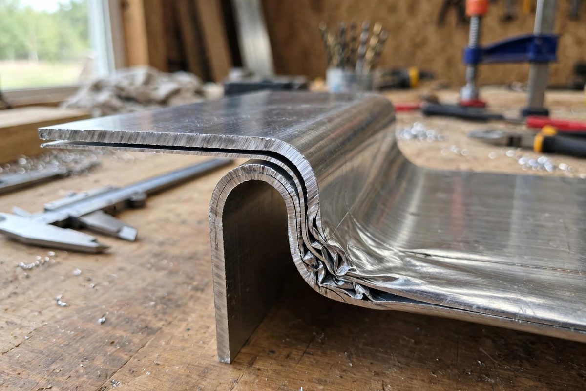
When sheet aluminum bends, the material on the inside of the bend compresses and the outside stretches, and the neutral axis, the layer that neither stretches nor compresses, shifts toward the inside. Bend deduction is the accounting for that shift: the amount by which the flat pattern must be shorter than the sum of the finished leg lengths. Get it wrong and every bent part comes out long or short; get it right and parts fit the first time. It is arithmetic, not art, but the arithmetic has to match the material.
Why the Flat Pattern Is Not Just Legs Added Together
A beginner measures the two legs of a finished bracket, adds them, cuts the flat to that length, and wonders why the bent part is too long. The bend itself consumes material differently than the flat legs do: the metal flows around the bend, and the developed length of the bend zone is shorter than the sum of the outside dimensions. Bend deduction is the correction factor that bridges the flat pattern and the finished part.
The size of the deduction depends on the material thickness, the inside bend radius, and the bend angle. Thicker material, tighter radii, and the specific alloy all change how the metal flows. Aluminum, being softer and more formable than steel, behaves a bit differently, which is why steel bend tables do not transfer directly.
The Variables: Thickness, Radius, and K-Factor
Three inputs drive the calculation. Material thickness is straightforward: measure it with calipers, because nominal gauge and actual thickness differ enough to matter. Inside bend radius is set by your tooling: the punch nose radius and the vee die opening together determine the radius the aluminum actually takes, and it is rarely exactly the punch radius.
The K-factor describes where the neutral axis sits within the thickness, expressed as a fraction of the thickness from the inside surface. For aluminum air-bent in typical tooling, the K-factor usually lands around 0.4 to 0.45, meaning the neutral axis sits a bit less than halfway through. Softer tempers push it slightly inward; harder tempers push it outward. The K-factor is the fudge factor that captures all the material behavior the simple geometry misses.
Working the Formula
The standard approach: bend deduction equals twice the outside setback minus the bend allowance, where the bend allowance is the developed length of the bend zone computed from the K-factor, thickness, radius, and angle. In practice, most shops use a bend table or calculator rather than deriving it by hand each time, and that is fine, as long as the table's assumptions match your tooling and material.
- Measure actual thickness; do not trust the nominal gauge stamp.
- Confirm the actual inside radius from a test bend, not from the punch marking.
- Use aluminum-specific K-factors; steel values will undershoot the deduction.
- Recalculate when changing temper; 5052-H32 and 6061-T6 do not bend alike.
The formula is only as good as its inputs. Garbage radius in, garbage deduction out. One careful test bend, measured and fed back into the numbers, beats any amount of theoretical precision.
Test Bends: Calibrating to Your Setup
The professional method is empirical: cut a test strip of the actual material, scribe lines at known distances, bend it in the actual tooling, and measure the result. The difference between the flat length and the finished legs is your real bend deduction for that material, temper, thickness, and tooling combination. Record it. That number is worth more than any published table, because it includes every quirk of your press brake.
Run test bends whenever something changes: new coil of material, different temper, different die, even a significant temperature swing in the shop. Aluminum's behavior is consistent within a setup and surprising across setups, and the test bend is how you stay on the consistent side.
Common Errors and Their Signatures
Parts consistently long after bending point to too little deduction: the flat pattern was cut too long because the calculation undervalued the bend zone. Parts consistently short point to too much. Random variation across identical parts points to inconsistent tooling setup or material, not to the math: check that the backgauge is seating the same way every time and that the material thickness is not varying.
Springback is the separate variable that gets blamed for deduction errors. Aluminum springs back after bending, especially in harder tempers, which changes the achieved angle but not the developed length. Compensate for springback with overbending or coining; do not fold it into the deduction, or you will be chasing two variables with one number.
Measure the thickness, verify the radius, pick the right K-factor, and prove it with a test bend. Bend deduction is one of the most satisfying calculations in the shop, because when it is right, the part just fits, and fitting the first time never gets old.
Related Guides
- Calculating K-Factor Values for Formed Sheet Copper: Bend a strip of copper and the outside stretches while the inside compresses; somewhere between them lies the neutral axis, the layer that neither
- High Frequency AC Balance Tuning for Thin TIG Aluminum: Thin aluminum punishes sloppy TIG settings: too much heat and it falls through, too little cleaning and the weld is contaminated, wrong balance and
- Fire Welding Temperature Windows in Coal Benches: Fire welding, forge welding steel in a coal forge, is the blacksmith's high-wire act: the steel must reach a temperature where its surfaces will fuse
- Shielding Gas Flow Rates for Short Circuit MIG: Short circuit MIG, the mode where the wire repeatedly touches the puddle and the arc extinguishes and restrikes dozens of times per second, is the
- Tramming Mill Heads to Eliminate Radial Scallops: A milling machine with its head out of tram cuts a subtle lie into every surface: instead of a flat plane, the cutter leaves a series of shallow