
Short circuit MIG, the mode where the wire repeatedly touches the puddle and the arc extinguishes and restrikes dozens of times per second, is the workhorse for thin material and out-of-position welding. It runs cooler and with less heat input than spray transfer, which also means its shielding gas envelope is more fragile. Flow rate is the variable that protects or exposes the weld: too little and the atmosphere contaminates the puddle; too much and the gas stream itself causes turbulence that drags air in. The right flow is a window, not a number.
What the Gas Actually Does
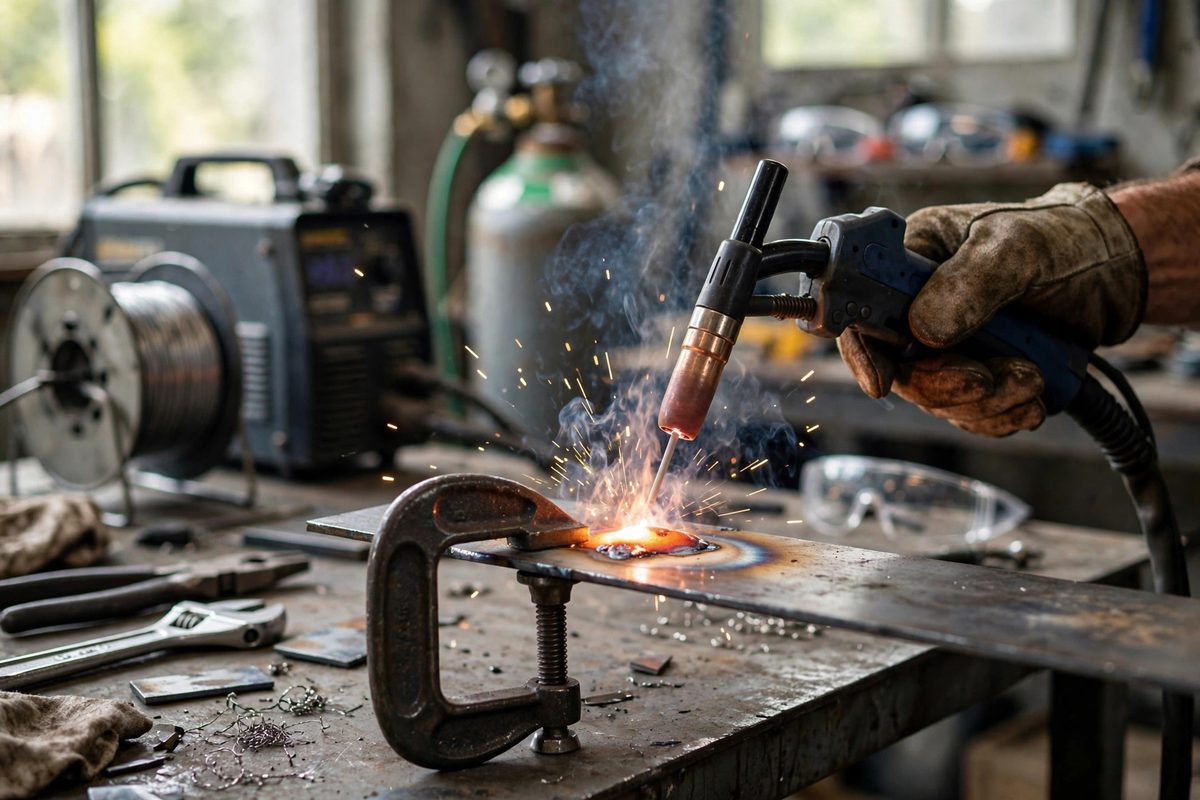
The shielding gas displaces the atmosphere around the arc and the molten puddle. Oxygen and nitrogen from the air dissolve into molten steel eagerly, causing porosity, brittleness, and a weld that looks fine until it is loaded. The gas envelope is a physical barrier, a laminar column of shielding gas flowing from the nozzle over the puddle, and its integrity depends on flow rate, nozzle geometry, and the surrounding air.
In short circuit transfer, the arc is repeatedly interrupted, and each interruption is a moment when the puddle is exposed. The gas coverage has to be continuous and stable through those cycles. That is why short circuit is fussier about gas than spray: the process itself keeps creating opportunities for contamination.
Finding the Flow Window
For typical short circuit MIG on steel with a standard nozzle, the working window usually sits around 20 to 30 cubic feet per hour (roughly 10 to 15 liters per minute), but that range assumes still air and a normal stickout. It is a starting point, not a specification. The correct flow for your setup is the lowest flow that gives clean, porosity-free welds, found by testing.
Start in the middle of the range and weld a test bead. Cut it or bend it, or at minimum inspect it closely: porosity shows as pinholes or wormholes in the bead face or in the ground cross-section. If the bead is clean, try reducing the flow slightly; if you see porosity, increase it. The goal is the minimum effective flow, because excess flow wastes gas and, past a point, hurts coverage.
Why More Gas Is Not Better
Cranking the flow feels like adding protection, but a high-velocity gas stream goes turbulent. Turbulence at the nozzle exit churns the shielding gas with the surrounding air, mixing atmosphere into the envelope instead of excluding it. The weld gets porosity from too much gas just as surely as from too little, and the operator, seeing porosity, often responds by turning the gas up further, which makes it worse.
- Watch the gas column: it should flow smoothly over the puddle, not blast it.
- Listen to the arc; a harsh, crackling instability can signal turbulence, not just electrical issues.
- Check for drafts first when porosity appears; no flow rate fixes a fan blowing across the weld.
- Oversized nozzles need more flow to fill; match the flow to the nozzle, not to habit.
Stickout, Nozzle, and Position Effects
Contact-tip-to-work distance changes the gas dynamics. Long stickout puts the nozzle farther from the puddle, so the gas column has farther to travel and more chance to disperse; it needs slightly more flow to compensate, though the better fix is usually to shorten the stickout. Short stickout keeps the nozzle close and the coverage tight.
Welding position matters too. Overhead and vertical welds fight gravity in the gas column as well as the puddle; a slightly higher flow helps maintain coverage when the gas wants to rise away from the joint. Outdoors or in drafty shops, windscreens or barriers around the work area do more for gas coverage than any flow adjustment. Shield the weld from wind before touching the regulator.
Gas Mix and the Short Circuit Mode
The standard mix for short circuit MIG on steel blends argon with carbon dioxide, commonly around three parts argon to one part CO2. The CO2 stabilizes the arc and improves penetration, while the argon keeps the arc smooth. Higher CO2 content increases spatter and requires slightly different flow behavior, since CO2 is denser and covers differently than argon-rich mixes.
Whatever mix you run, set the flow for that mix and that job, and verify with a test weld. The regulator number is a means to an end; the weld is the end. When the bead is clean, the flow is right, whatever the gauge says.
Start mid-range, test downward to the minimum that stays clean, shield the work from drafts, and remember that turbulence is the enemy that looks like a friend. Gas coverage is a laminar column, not a fire hose, and the quiet flow protects better than the blast.
Related Guides
- High Frequency AC Balance Tuning for Thin TIG Aluminum: Thin aluminum punishes sloppy TIG settings: too much heat and it falls through, too little cleaning and the weld is contaminated, wrong balance and
- Calculating Bend Deduction in Sheet Aluminum: When sheet aluminum bends, the material on the inside of the bend compresses and the outside stretches, and the neutral axis, the layer that neither
- Fire Welding Temperature Windows in Coal Benches: Fire welding, forge welding steel in a coal forge, is the blacksmith's high-wire act: the steel must reach a temperature where its surfaces will fuse
- Tramming Mill Heads to Eliminate Radial Scallops: A milling machine with its head out of tram cuts a subtle lie into every surface: instead of a flat plane, the cutter leaves a series of shallow
- Calculating K-Factor Values for Formed Sheet Copper: Bend a strip of copper and the outside stretches while the inside compresses; somewhere between them lies the neutral axis, the layer that neither