
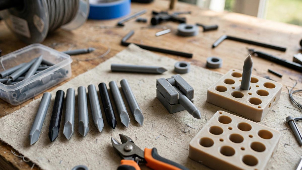
Printed pins that press into printed holes are the bread and butter of 3D-printed assemblies: hinges, joints, locators, fasteners. Getting the friction fit right is a small geometry problem with a big payoff, and the chamfer on the pin's leading edge is the detail that makes insertion work in the real, imperfect world of printed parts.
How friction fit works in printed plastic
A friction fit holds by interference: the pin is slightly larger than the hole, and the plastic deforms elastically to grip it. Printed plastics are less forgiving than machined metal; the layer lines create a rough surface, the dimensions vary with print settings, and the material creeps under sustained pressure. The interference must be small enough to assemble by hand but large enough to hold: typically a few hundredths of a millimeter of diametral interference for small pins. More than that risks splitting the hole part; less than that gives a pin that falls out.
The chamfer's job
The chamfer on the pin's leading edge guides the pin into the hole, centering it and easing the start of the interference. Without a chamfer, the pin's sharp edge catches on the hole's rim, shaving plastic and jamming; the assembler pushes harder, the parts flex, and the fit is ruined before it starts. A chamfer of about forty-five degrees, extending back roughly the amount of the interference plus a little, turns a fight into a smooth press. It also forgives the elephant's foot, the slight flare at the base of printed parts, that would otherwise block entry.
Relief clearance behind the chamfer
Behind the chamfer, the pin's full diameter engages the hole, but a slight relief, a short section just under full diameter right behind the chamfer, can help. The relief gives displaced plastic somewhere to go during insertion and reduces the peak insertion force. Keep the relief short and shallow; too much relief shortens the effective grip length and weakens the hold. For most small pins, the chamfer alone suffices, and the relief is a refinement for tight fits or stiff materials.
Sizing the interference
Size the pin and hole from your printer's actual behavior, not from the CAD numbers. Print a test coupon: a small plate with holes in graduated sizes and pins to match, then find the combination that presses in firmly by hand and holds. Printer calibration, filament, and slicer settings all shift the effective sizes, so the test coupon is specific to your setup. Record the winning dimensions; they become your standard pin and hole sizes for future designs. Re-test when anything in the printing chain changes.
Orientation and layer lines
Print orientation affects the fit. A pin printed vertically has layer lines around its circumference, giving a slightly rough, grippy surface; a hole printed vertically has the same texture inside. This roughness actually helps friction fit, but it also means the effective diameters differ from horizontal prints. Design the pin and hole to print in the orientations they will use, and test in those orientations. A fit proven in one orientation may not transfer to another.
Designing for assembly and service
Consider how the pin will be installed and whether it ever needs to come out. A pin that must be removable wants less interference and perhaps a head or grip for extraction; a permanent pin can run tighter. Provide lead-in on the hole side too, a slight countersink, which works with the pin's chamfer to guide assembly. Think about the assembler's hands: a pin too small to grip cannot be pressed in no matter how perfect the geometry. Design the fit for the human as well as the plastic.
Chamfer the leading edge, size the interference from test prints, mind the orientation, and design for the assembler's hands. The pins will press in smoothly and stay put, which is everything a friction fit promises.
Related Guides
- Printable Snap Joint Clearances for Hard Polycarbonate: Snap-fit joints, the cantilever hooks and annular rings that click assemblies together without fasteners, are among the most satisfying features to
- Snap Fit Tab Beam Deflection Tolerances in PETG Files: Snap-fit tabs are the 3D printer's answer to screws: a cantilever beam that bends aside during assembly and springs back to lock parts together. They
- Calculating Living Hinge Deflection in TPU Parts: A living hinge, a thin flexible section printed as part of the whole, lets a 3D-printed part bend repeatedly without hardware. In TPU, the flexible
- Living Hinge Fatigue Calculations for TPU Prints: A living hinge printed in TPU is one of those designs that either lasts years or snaps in a week, and the difference is geometry, not luck. Unlike