
Snap-fit joints, the cantilever hooks and annular rings that click assemblies together without fasteners, are among the most satisfying features to design for 3D printing. But a snap joint designed for injection molding will usually fail when printed: the layer lines, the material properties, and the dimensional realities of printing all differ from molding. Hard polycarbonate, prized for its toughness and temperature resistance, has its own requirements for snap clearance, deflection, and geometry. Designing printable snap joints for this material means respecting both the polymer's character and the printer's limitations.
How snap joints work
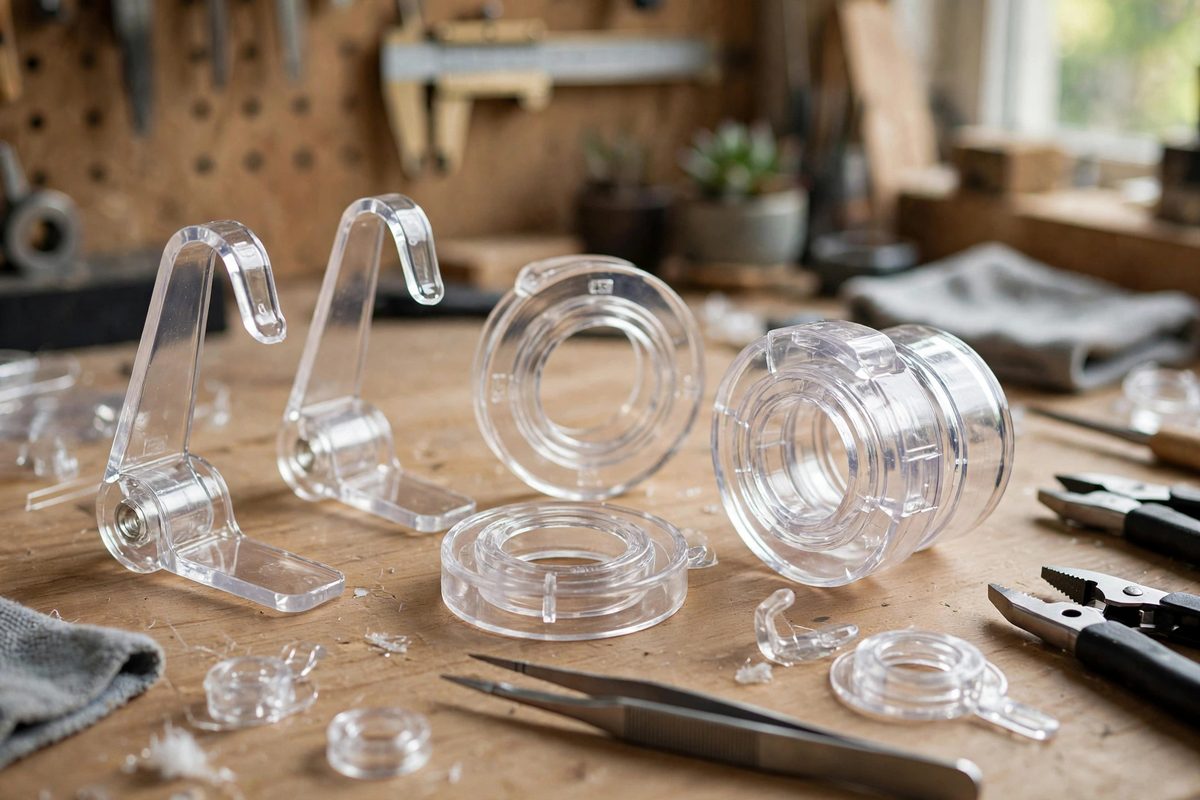
A cantilever snap joint is a beam with a hook: during assembly, the hook deflects as it passes over its mating feature, then springs back into an undercut, locking the parts together. The design variables are the beam's length, thickness, and width, which set its stiffness; the hook's lead-in angle, which sets the assembly force; and the undercut depth, which sets the retention force. The beam must deflect enough to assemble without exceeding the material's allowable strain, and the hook must engage deeply enough to resist the service loads. Clearance enters in the mating dimensions: the parts must fit together with enough room for the deflection to occur, but not so much room that the assembly rattles or the hook fails to engage. Every dimension is a tradeoff, and the tradeoffs are material-specific.
Polycarbonate's material character
Polycarbonate is tough, with high impact resistance and good ductility, which makes it forgiving of the deflection snap joints require; it bends rather than snapping, within its limits. It also has a relatively high modulus, meaning a given beam geometry is stiffer than in a softer polymer, so polycarbonate snap beams typically run thinner or longer than their equivalents in more flexible materials. The material's allowable strain for repeated assembly, lower than its one-time yield strain, governs designs meant to be snapped repeatedly; a joint that survives one assembly may fatigue over dozens of cycles if the strain is too high. Design for the service life: a joint assembled once at the factory can use more of the material's strain budget than a joint the user opens weekly. Printed polycarbonate's properties also depend on print quality: good layer adhesion is essential, since delamination between layers is the characteristic failure of printed snap beams.
Clearance guidelines for printed fits
Printed dimensions vary with the printer, the material batch, and the geometry, so snap joint clearances must accommodate real printed tolerances rather than nominal CAD dimensions. As a starting point, design mating clearances in the range of a tenth to two-tenths of a millimeter per side for features that must slide during assembly, tightening only where the specific printer has proven it can hold tolerance. The hook and undercut engagement should be designed with the clearance subtracted: the nominal interference that creates the snap must survive the worst-case tolerance stack. Print test coupons of the joint geometry before committing to the full part; a small test piece with several clearance variants reveals the printer's actual behavior in an hour, while a failed full print wastes a day. Measure the test pieces and adjust the CAD to the measured reality, not the nominal intent.
Orienting the joint for layer strength
Print orientation decides whether the snap beam is strong or fragile. The beam should be oriented so its bending stresses run along the layer lines rather than across them: layers delaminate under the tensile stress of bending far more readily than they fail along the extrusion direction. This usually means printing the snap beam lying flat, with its width in the layer plane, so the deflection bends the beam within the strong direction. Avoid orienting the beam vertically, where each layer boundary becomes a potential fracture plane at the beam's root, the highest-stress point. The hook's lead-in faces also print more cleanly in favorable orientations; a hook printed with its engaging surfaces as overhangs will have the rough finish and dimensional inaccuracy of unsupported overhangs exactly where precision matters most.
Design details that prevent failure
Several details separate working snap joints from frustrating ones. Fillet the beam's root generously; sharp internal corners concentrate stress and are where printed beams crack, while a good fillet distributes it. Taper the beam slightly from root to tip so the bending strain distributes along its length rather than concentrating at the root. Keep the lead-in angle gentle, around thirty degrees or less from the assembly direction, to keep assembly forces reasonable; steep hooks require brutal force and punish any dimensional error. Provide a defined stop so the parts cannot be over-inserted past the snap point, which would strain or break the beam. And consider the disassembly path: if the joint must come apart, design access for a tool or a flex point; a snap joint with no planned disassembly becomes a destructive disassembly.
Testing and iteration
Test snap joints the way they will be used: assemble and disassemble the design-life number of cycles, checking for whitening at the beam root, which signals approaching fatigue failure, and for loosening engagement, which signals wear or creep. Test at the temperature extremes the product will see, since polycarbonate's properties shift with temperature and a joint perfect at room temperature may be brittle in the cold. Iterate the clearances based on measured test results, and keep the test coupons as a reference for future designs. A proven snap joint geometry, documented with its clearances and test results, becomes a reusable design asset worth more than the part it was created for.
Design printable polycarbonate snap joints around the material's toughness and the printer's tolerances: size beams for allowable strain over the service life, clearance for printed reality verified by test coupons, orient for layer strength, fillet and taper the details, and cycle-test to the design life. The click of a well-designed snap is the sound of all these decisions agreeing.
Related Guides
- Chamfer Relief Clearance for Friction Fit Printable Pins: Printed pins that press into printed holes are the bread and butter of 3D-printed assemblies: hinges, joints, locators, fasteners. Getting the
- Snap Fit Tab Beam Deflection Tolerances in PETG Files: Snap-fit tabs are the 3D printer's answer to screws: a cantilever beam that bends aside during assembly and springs back to lock parts together. They
- Calculating Living Hinge Deflection in TPU Parts: A living hinge, a thin flexible section printed as part of the whole, lets a 3D-printed part bend repeatedly without hardware. In TPU, the flexible
- Living Hinge Fatigue Calculations for TPU Prints: A living hinge printed in TPU is one of those designs that either lasts years or snaps in a week, and the difference is geometry, not luck. Unlike