
A 3D-printed drill jig earns its keep by placing holes exactly where they belong, repeatedly. The drill bushing, the hardened sleeve the bit runs through, is what makes the jig accurate instead of approximate. But a bushing pressed into a plastic bore needs the right clearance: too tight and it will not install or it cracks the print; too loose and it wobbles, defeating the purpose. Getting bushing fits right in printed plastic is a specific skill.
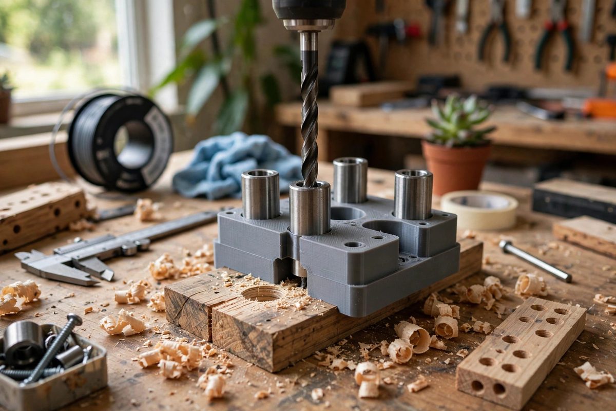
Why bushings matter in printed jigs
A drill bit running directly in a printed hole wallows the hole out within a few uses; plastic cannot resist a spinning steel edge. The bushing takes the wear instead: its hardened inner bore guides the bit precisely, and its outer body anchors into the jig. Standard press-fit bushings are sized for metal bores, so the printed bore must be designed to grip them correctly. The bushing also sets the hole's perpendicularity; a bushing installed crooked drills crooked holes forever, so the bore must hold it square.
Designing the bore for a press fit in plastic
Plastic creeps and printed bores are never perfectly round, so the textbook metal press-fit numbers do not transfer directly. A practical approach: model the bore 0.1 to 0.2mm smaller than the bushing's outer diameter for common jig plastics like PETG or ABS, and test with a printed coupon before committing to the full jig. PLA is stiffer and more brittle; use the lighter end of the interference range and consider a slightly longer bore to distribute the stress. If the bushing must be removable, design for a slip fit with a set screw or a retaining plate instead of a press fit.
Bore geometry and print orientation
Print the bore axis vertically (along Z) whenever possible; vertical holes print rounder than horizontal ones, which suffer from layer-step faceting. Make the bore long enough to support the bushing fully, at least as long as the bushing's outer body, and add a small chamfer at the entry to guide installation. Keep wall thickness around the bore generous, at least 3 to 4mm of solid material, since the press fit puts the surrounding plastic in tension. Thin walls around a pressed bushing will crack, sometimes days later as the plastic relaxes.
Installation technique
Press the bushing in straight using an arbor press or a vise with parallel jaws; hammering a bushing into plastic invites both cracking and crooked installation. Support the jig directly under the bore so the pressing force does not flex the part. If the fit is tighter than expected, stop and ream the bore slightly rather than forcing it; a bushing installed under protest will stress-crack the jig later. For critical jigs, install the bushing with the jig at room temperature and let it sit a day before use, so any relaxation happens before the jig goes to work.
Verifying the finished jig
After installation, check the bushing for square with a small square or an indicator, and drill test holes in scrap to verify position. Measure the test holes, not the bushing; the holes are the jig's actual output. If holes drift from the intended position, the error is in the jig's design or the bushing's installation, and it is better found in scrap than in the workpiece. Log the bore size that worked for your printer, plastic, and bushing combination; it becomes a shop standard.
Size the bore for plastic's reality, print it round, press it straight, and verify with holes. The jig will then do what jigs are for: the same right hole, every time.
Related Guides
- Standard Steel Bushing Fits for 3D Drill Guides: A 3D-printed drill guide earns its keep when a spinning drill bit meets a hardened steel bushing instead of soft plastic. The bushing guides the bit
- Embedding Hex Nuts and Threaded Inserts in Drill Jigs: A 3D-printed drill jig lives a hard life: clamps squeeze it, drill bits wander against its guide holes, and bolts get threaded in and out dozens of
- Hardened Steel Bushing Tolerances for Drilling Guides: Drill bushings, hardened steel sleeves pressed into jigs and fixtures, are what make a drilling guide a precision tool rather than a suggestion. The
- Zero-Tolerance V-Groove Alignment in 3D Printed Guides: Printed jigs and guides often need to locate a rod, shaft, or edge with real precision: a drill guide, a cutting jig, a measurement fixture. The