
Drill bushings, hardened steel sleeves pressed into jigs and fixtures, are what make a drilling guide a precision tool rather than a suggestion. The drill bit rides inside the bushing, constrained to the intended axis and position, while the bushing's hardness resists the wear that would quickly ovalize a plain hole. But the bushing only performs if its tolerances are right: the fit between bushing and jig body, the fit between bushing and drill, and the bushing's own geometry all have specified tolerances, and each serves a purpose. Understanding these tolerances lets you specify, install, and verify bushings that hold their accuracy over thousands of holes.
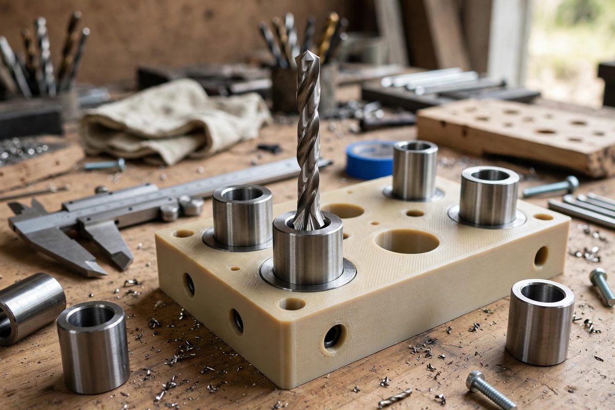
What the bushing does
A drill bushing serves three functions simultaneously. It locates the drill radially, holding the bit on the intended axis against the side forces of cutting. It guides the drill's entry, preventing the walking and skating that plague hand-started holes. And it survives: the hardened bore resists abrasion from the spinning bit far longer than any jig body material, preserving the guide's accuracy over its service life. Each function depends on tolerance: location accuracy on the bushing's position in the jig, guidance on the bushing-to-drill clearance, and longevity on the hardness and the press fit that keeps the bushing from migrating. A bushing is a small part carrying large responsibilities, which is why its tolerances are specified rather than assumed.
Bushing-to-drill clearance
The inside diameter of the bushing must clear the drill bit enough to let it spin freely without binding, but tightly enough to actually guide it. Standard practice uses a small, defined clearance: enough that the bit never seizes from heat expansion or chip packing, tight enough that the bit cannot wander measurably. Too tight, and the bit binds, overheats, and either seizes in the bushing or snaps; too loose, and the guide's accuracy degrades toward that of a freehand hole. The clearance is specified as a tolerance class on the bore relative to the nominal drill size, and quality bushings are manufactured and inspected to hold it. When selecting bushings, match the bore tolerance to the drill size actually used, not the nominal size on the drawing; a worn or undersized bit in a correct bushing still drills an oversized, wandering hole.
Press fit into the jig body
The bushing's outside diameter is sized for a press fit into the jig body's bored hole: the bushing is slightly larger than the hole, and pressing it in creates the interference that locks it permanently. The interference must be enough to prevent any movement under drilling forces and thermal cycling, but not so much that pressing cracks the jig body or distorts the bushing's bore; a distorted bore loses the carefully specified drill clearance. Standard press fit allowances for bushing sizes are published in machinery references and should be followed rather than improvised. Bore the jig body's holes to the specified size with a proper boring operation, not a drilled hole; a drilled hole's tolerance and finish are inadequate for a reliable press fit. Press the bushing in straight with an arbor press, supporting the jig body properly, and verify the bore afterward.
Bushing types and their tolerance implications
Several bushing styles serve different needs. Press-fit headed bushings are the standard for permanent installations, located axially by the head. Slip-fit renewable bushings allow replacement without disturbing the jig, using a liner bushing pressed into the body and a slip bushing that locks into the liner; this two-stage system adds tolerance interfaces, and each must be correct for the assembly to hold accuracy. Threaded or clamped guide bushings suit adjustable fixtures. The choice affects the tolerance chain: every interface between components adds its variation to the final drill position. Keep the chain as short as the application allows, and tolerance each interface deliberately rather than letting the stack accumulate unexamined.
Installation procedure
Install bushings with care proportional to their precision. Bore the receiving holes to size, checking with a bore gauge, and chamfer the entrance lightly to guide the bushing's entry. Chill or lightly oil the bushing per standard practice to ease pressing; never hammer a bushing in, since impact loading can crack the hardened steel or bell-mouth the bore. Press steadily until the head seats firmly against the jig face, with no gap and no rocking. After installation, verify: check the bore with a gauge pin or the actual drill for free rotation without perceptible play, and verify the bushing's position against the jig's datum with an indicator. A bushing installed but unverified is an assumption, not a guide.
Wear, inspection, and replacement
Bushings wear, and worn bushings drill bad holes confidently. Inspect the bore periodically with gauge pins; a bore that has grown beyond its tolerance, or that shows bell-mouthing at the entry from thousands of drill starts, is due for replacement. Track hole counts for production jigs to schedule replacement before wear affects quality; the bushing's service life in holes is predictable enough for planning. Replace press-fit bushings by pressing out the old and pressing in the new, re-verifying the bore and position afterward. Keep spare bushings on hand for critical jigs; the cost of a spare is trivial against the cost of a jig down waiting for parts. The drilling guide is only as accurate as its most worn bushing, so the inspection schedule is part of the tolerance system.
Drill bushing tolerances form a chain: bore clearance that guides without binding, press fit that locks without distorting, positioned accurately in a properly bored jig body, inspected on schedule. Specify each interface deliberately, install with presses not hammers, verify after installation, and replace on wear. Precision in the small steel sleeve becomes precision in every hole it guides.
Related Guides
- Standard Steel Bushing Fits for 3D Drill Guides: A 3D-printed drill guide earns its keep when a spinning drill bit meets a hardened steel bushing instead of soft plastic. The bushing guides the bit
- Drill Guide Bushing Clearances in 3D Jigs: A 3D-printed drill jig earns its keep by placing holes exactly where they belong, repeatedly. The drill bushing, the hardened sleeve the bit runs
- Zero-Tolerance V-Groove Alignment in 3D Printed Guides: Printed jigs and guides often need to locate a rod, shaft, or edge with real precision: a drill guide, a cutting jig, a measurement fixture. The
- Embedding Hex Nuts and Threaded Inserts in Drill Jigs: A 3D-printed drill jig lives a hard life: clamps squeeze it, drill bits wander against its guide holes, and bolts get threaded in and out dozens of