
Printed jigs and guides often need to locate a rod, shaft, or edge with real precision: a drill guide, a cutting jig, a measurement fixture. The V-groove is the classic solution, cradling a cylinder on two lines of contact that center it automatically. Getting a printed V-groove to align with zero tolerance takes deliberate design, because printed plastic is not a machined surface.
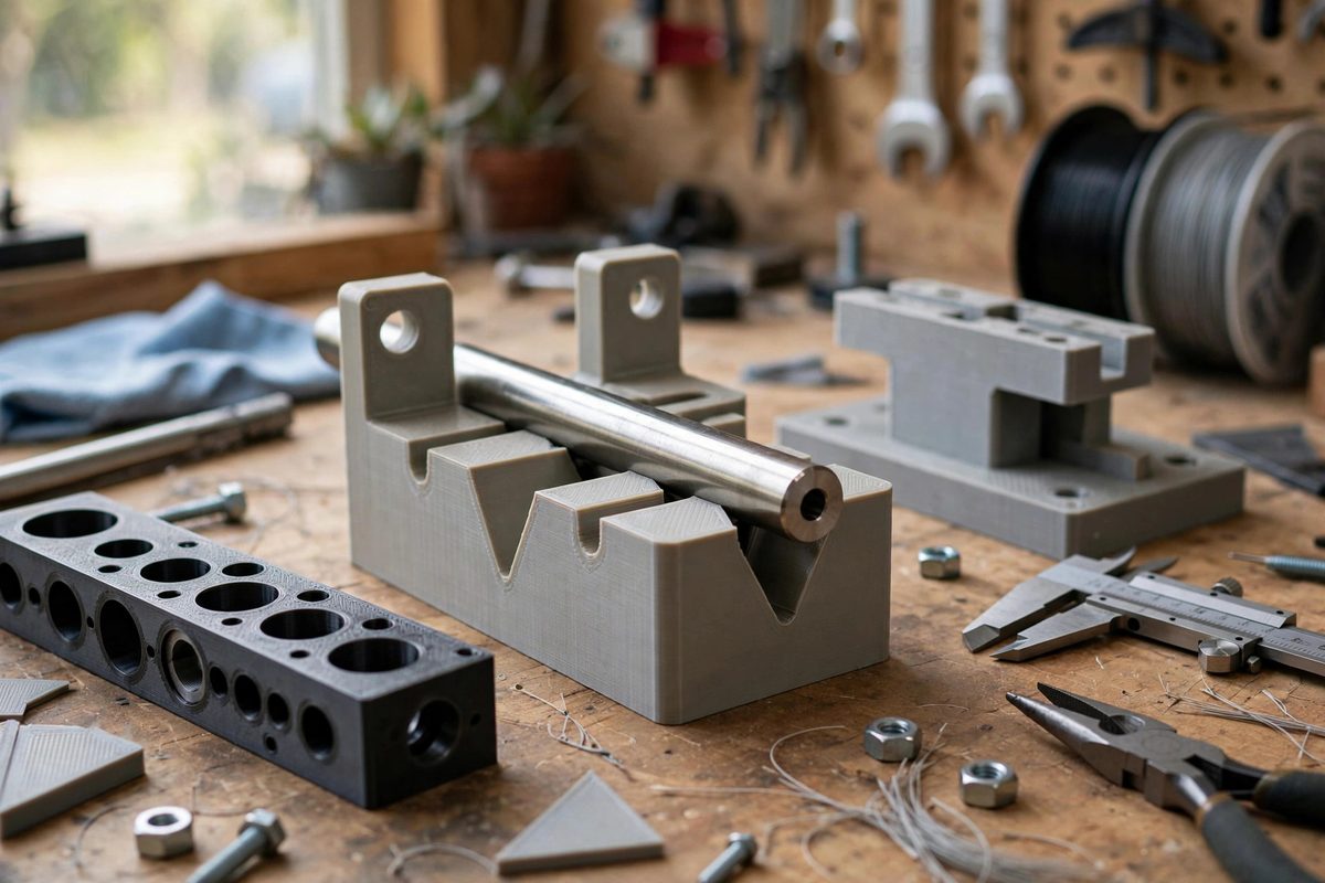
Why the V-groove centers
A cylinder dropped into a V-groove touches each face along one line, and those two contact lines force the cylinder's axis onto the groove's center plane. The geometry is self-centering: any sideways displacement increases the contact on one side and the groove pushes back. This is why V-blocks are standard metrology tooling. In a printed guide, the same geometry works, but the contact lines are on layered plastic, which is rougher and more compliant than ground steel. The principle holds; the execution needs care.
The zero-tolerance challenge
Zero tolerance here means the located part sits exactly where the design intends, with no slop. Printed parts have dimensional variation: the groove may print slightly wide or narrow, the faces may have layer steps, and the plastic may shrink unevenly. Designing the groove to nominal size and hoping is not a strategy. Instead, design the groove slightly undersized and plan to fit it: the cylinder should need a light press to seat, with the plastic's compliance taking up the variation. Test and adjust the CAD dimension until the fit is right on your printer.
Groove angle and contact
The standard V angle is ninety degrees, which gives good centering with reasonable contact pressure. Wider angles center less positively; narrower angles wedge the cylinder and make it hard to insert and remove. For a guide where the rod slides, ninety degrees with a smooth finish is the sweet spot. Consider the contact length too: a longer groove averages out local print irregularities, while a short groove telegraphs every bump. Make the groove as long as the design allows.
Printing for the best groove
Orientation is everything. Print the groove so its faces are as smooth as possible: faces printed vertically show layer steps, while faces at an angle or printed horizontally are smoother. Often the best orientation has the V opening upward, with the faces built as overhangs, which requires good overhang performance or supports. Use fine layer heights on the groove faces; the extra print time buys surface quality where it matters. A well-oriented print needs no post-processing; a poorly oriented one cannot be sanded into precision.
Verification with the real part
Verify the groove with the actual rod or shaft it will locate, not with calipers alone. Seat the part in the groove and check for rock: any rocking means the contact is not as designed. Check the part's position against a reference; it should repeat exactly every time the part is seated. If the fit is loose, reduce the groove dimension in CAD and reprint; if it binds, open it slightly. Iterate on test pieces, not on the final jig, and keep the proven dimension as your standard V-groove size.
Wear and longevity
Plastic V-grooves wear with use, especially with steel rods sliding in them. For a jig used occasionally, the wear is negligible; for a production fixture, consider a replaceable groove insert or a harder material. Design the groove as a separate insert from the start if wear is a concern; replacing a small insert beats reprinting the whole jig. Inspect the groove periodically by repeating the seating test; when the part no longer repeats position, the groove is done.
Design the groove slightly tight, print it in the smoothest orientation, verify with the real part, and plan for wear. The printed V-groove will locate like the metrology tool it imitates.
Related Guides
- Standard Steel Bushing Fits for 3D Drill Guides: A 3D-printed drill guide earns its keep when a spinning drill bit meets a hardened steel bushing instead of soft plastic. The bushing guides the bit
- Drill Guide Bushing Clearances in 3D Jigs: A 3D-printed drill jig earns its keep by placing holes exactly where they belong, repeatedly. The drill bushing, the hardened sleeve the bit runs
- Hardened Steel Bushing Tolerances for Drilling Guides: Drill bushings, hardened steel sleeves pressed into jigs and fixtures, are what make a drilling guide a precision tool rather than a suggestion. The
- Embedding Hex Nuts and Threaded Inserts in Drill Jigs: A 3D-printed drill jig lives a hard life: clamps squeeze it, drill bits wander against its guide holes, and bolts get threaded in and out dozens of