
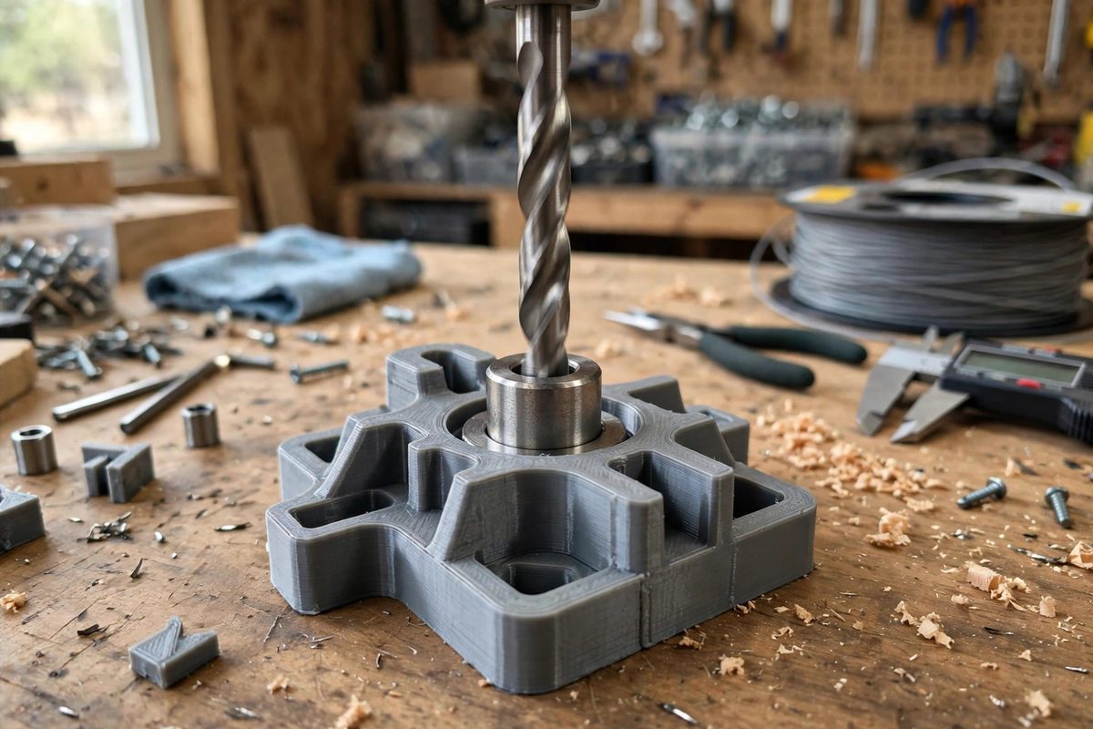
A 3D-printed drill guide earns its keep when a spinning drill bit meets a hardened steel bushing instead of soft plastic. The bushing guides the bit true, the plastic body holds the bushing in position, and the whole jig drills hole after hole without wandering. The relationship between bushing and printed bore is where the design lives or dies: too loose and the bushing spins and rattles, too tight and it cracks the print going in.
Why Bushings, Not Bare Plastic
A drill bit spinning in a plastic hole wears the hole oversize within a few dozen holes, especially in PLA, which softens under the friction heat. A press-fit steel bushing takes the wear instead, and when it eventually loosens, you press it out and replace it without reprinting the jig. Standard drill bushings come with a flanged head that registers against the jig face, setting a repeatable depth and giving the press fit a shoulder to seat against. Buy the bushings first, then design the printed bores around their actual measured dimensions.
Fit Classes in Plain Terms
In machinist terms, a press fit is an interference fit: the bore is slightly smaller than the bushing, and the bushing wedges in permanently. A slip fit has clearance so the bushing slides in and out, useful for replaceable liners. A light press fit (roughly a few ten-thousandths of interference) is the target for printed jigs: enough grip to keep the bushing from rotating under drilling torque, but not so much that installation splits the print. Because FDM prints are dimensionally sloppy compared to machined metal, you design for a range, not a single number.
Sizing the Printed Bore
Measure your bushing's outside diameter with calipers, then size the printed bore about 0.1 to 0.2 mm under that dimension for a light press fit in PLA or PETG. This sounds enormous by machining standards, but printed bores shrink and vary: the slicer's hole compensation, the filament's shrinkage, and even the infill pattern shift the true diameter. Print a test coupon with bores in 0.05 mm steps around your target, press a spare bushing into each, and use whichever size seats with firm hand pressure plus a light tap. Record the winning bore size on the STL filename or in the print notes, because it is specific to your printer and filament.
Wall Stock Around the Bore
Press fits create hoop stress, and thin printed walls cannot take it. Give each bushing bore at least 4 to 5 mm of solid wall in every direction, printed with enough perimeters that the bore wall is effectively solid plastic. A boss (a raised cylindrical pad) around each bore is cheap insurance: it adds wall stock exactly where the stress is and gives the flange a flat seating surface. Avoid placing bores near thin edges or between sparse infill; a bushing pressed into an under-walled bore will oval the hole and eventually spin.
Installation Without Cracking
Warm the bushing slightly (not the print) before pressing, and press straight with an arbor press or a vise, never hammered in at an angle. The flanged head should seat fully against the jig face with no gap; a gap means the bore is undersized and the bushing is riding on interference instead of seated. If a bushing ever spins in service, pull it, add a drop of retaining compound, and re-press; that is a repair, not a redesign. And drill a test hole in scrap after every new bushing installation, because a bushing that pressed in slightly crooked drills holes that are slightly off location.
A drill guide with properly fitted steel bushings is a precision tool that happens to have a plastic body. Size the bore to your actual bushings with test coupons, give the bores real wall stock, press them in straight, and the jig will drill true holes long after a bare-plastic guide has worn itself useless.
Related Guides
- Drill Guide Bushing Clearances in 3D Jigs: A 3D-printed drill jig earns its keep by placing holes exactly where they belong, repeatedly. The drill bushing, the hardened sleeve the bit runs
- Hardened Steel Bushing Tolerances for Drilling Guides: Drill bushings, hardened steel sleeves pressed into jigs and fixtures, are what make a drilling guide a precision tool rather than a suggestion. The
- Zero-Tolerance V-Groove Alignment in 3D Printed Guides: Printed jigs and guides often need to locate a rod, shaft, or edge with real precision: a drill guide, a cutting jig, a measurement fixture. The
- Embedding Hex Nuts and Threaded Inserts in Drill Jigs: A 3D-printed drill jig lives a hard life: clamps squeeze it, drill bits wander against its guide holes, and bolts get threaded in and out dozens of